
")
")
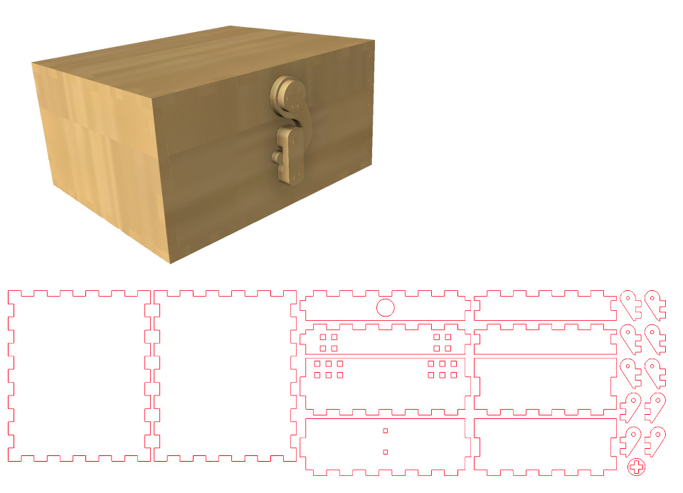 When designing boxes from sheet material, I use finger joints to connect the various parts. Adding all those finger joints one by one is quite a task, but it can also be partially automated in Fusion 360. When designing boxes from sheet material, I use finger joints to connect the various parts. Adding all those finger joints one by one is quite a task, but it can also be partially automated in Fusion 360. |
 I design my boxes in Fusion 360. When designing, I take into account that I'm working with sheet material. Therefore, I build my design from the beginning using sheets rather than volumes. This makes it easier to actually create the box later on. In this guide, I'll show you how to make a simple box without a lid using finger joints. I assume you have some basic knowledge of Fusion for this explanation. I design my boxes in Fusion 360. When designing, I take into account that I'm working with sheet material. Therefore, I build my design from the beginning using sheets rather than volumes. This makes it easier to actually create the box later on. In this guide, I'll show you how to make a simple box without a lid using finger joints. I assume you have some basic knowledge of Fusion for this explanation. |
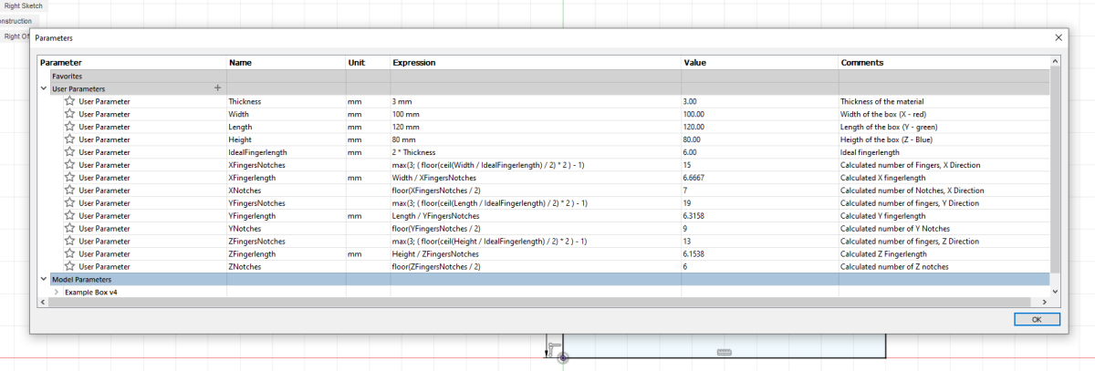
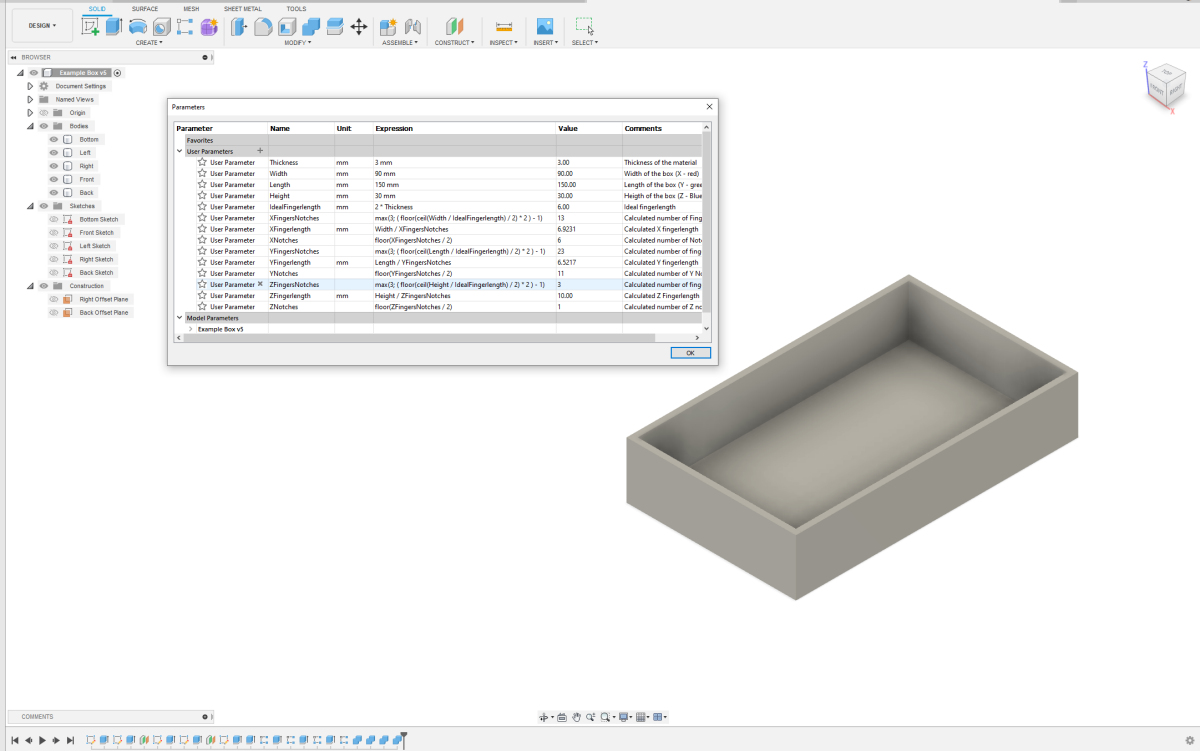
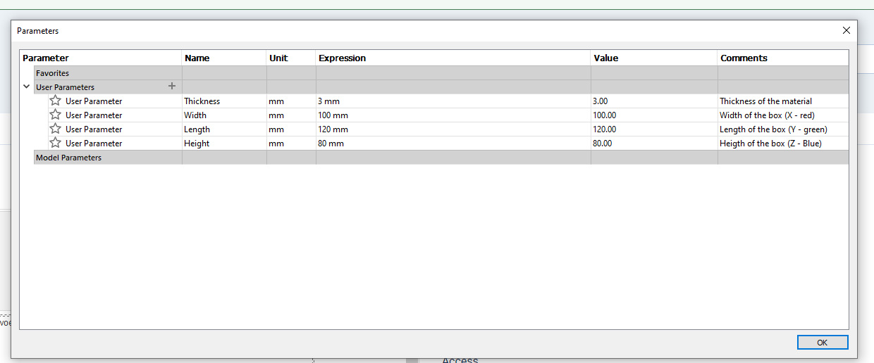 Before I start my design, I'll specify some basic parameters (Modify - Change Parameters). I'll specify the material thickness (Thickness) and the outer dimensions of the box. Now I can use these parameters consistently. If I need to adjust the box later on, I can easily modify the values in the parameter table. Before I start my design, I'll specify some basic parameters (Modify - Change Parameters). I'll specify the material thickness (Thickness) and the outer dimensions of the box. Now I can use these parameters consistently. If I need to adjust the box later on, I can easily modify the values in the parameter table. |
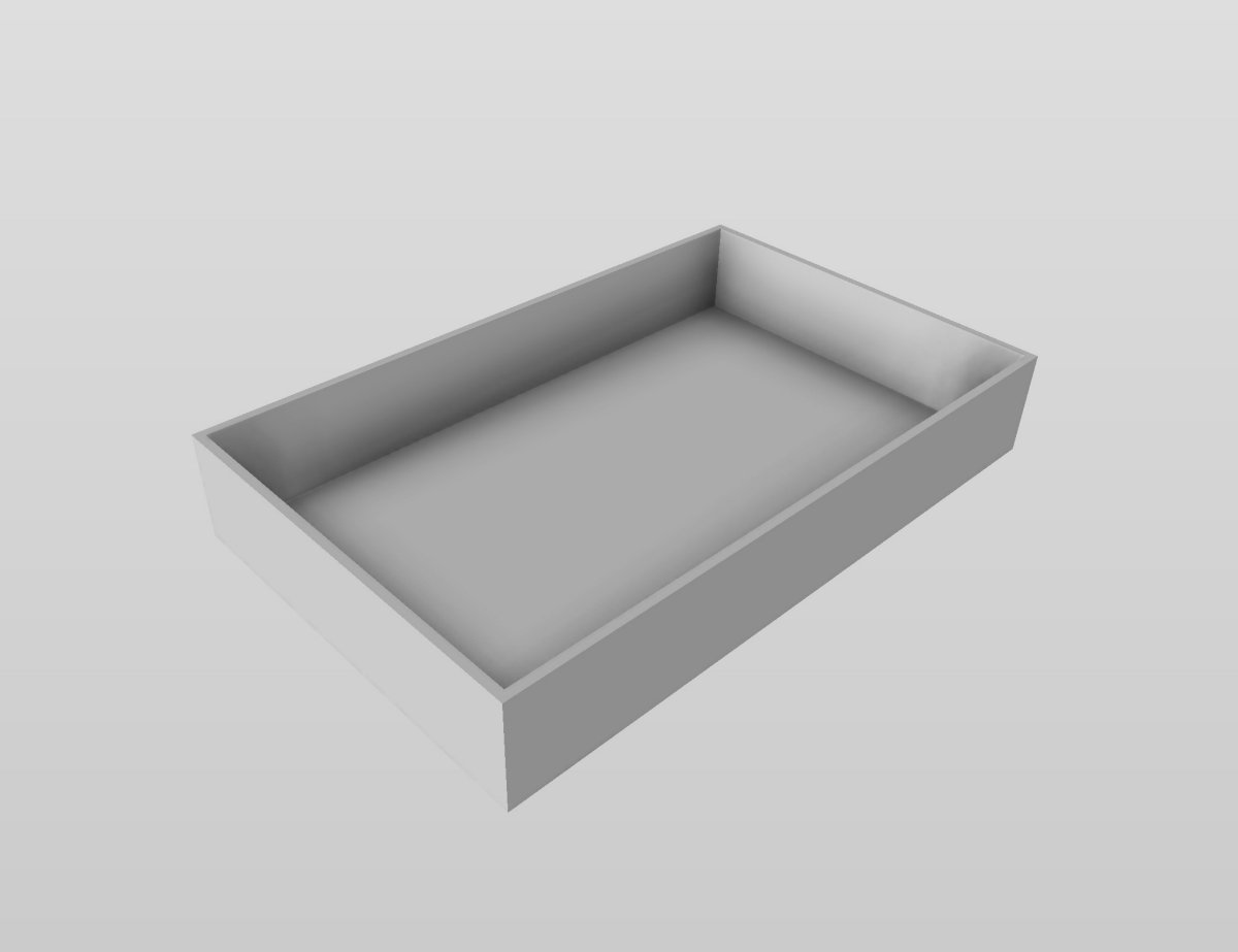
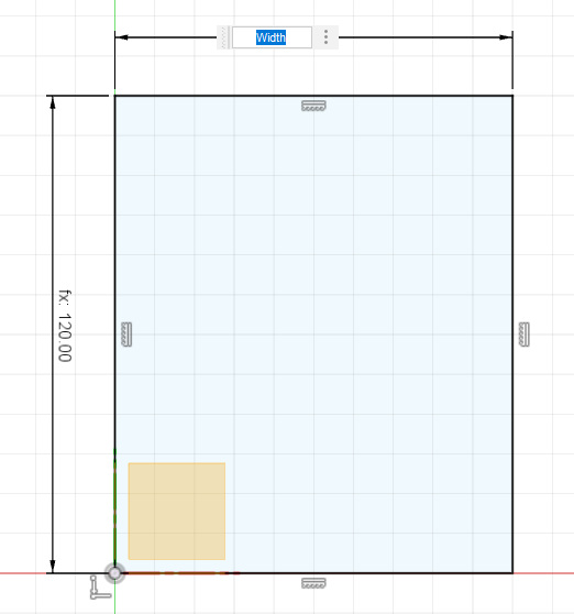 Now that I've specified these values, I can use them in the sketch. I'll start by creating a sketch for the bottom plate of the box. This is a simple rectangle. Instead of specifying 100mm for the width, I'll use the parameter Width. Similarly, for the length, I'll use a parameter, Length, instead of a specific value. Now that I've specified these values, I can use them in the sketch. I'll start by creating a sketch for the bottom plate of the box. This is a simple rectangle. Instead of specifying 100mm for the width, I'll use the parameter Width. Similarly, for the length, I'll use a parameter, Length, instead of a specific value. |
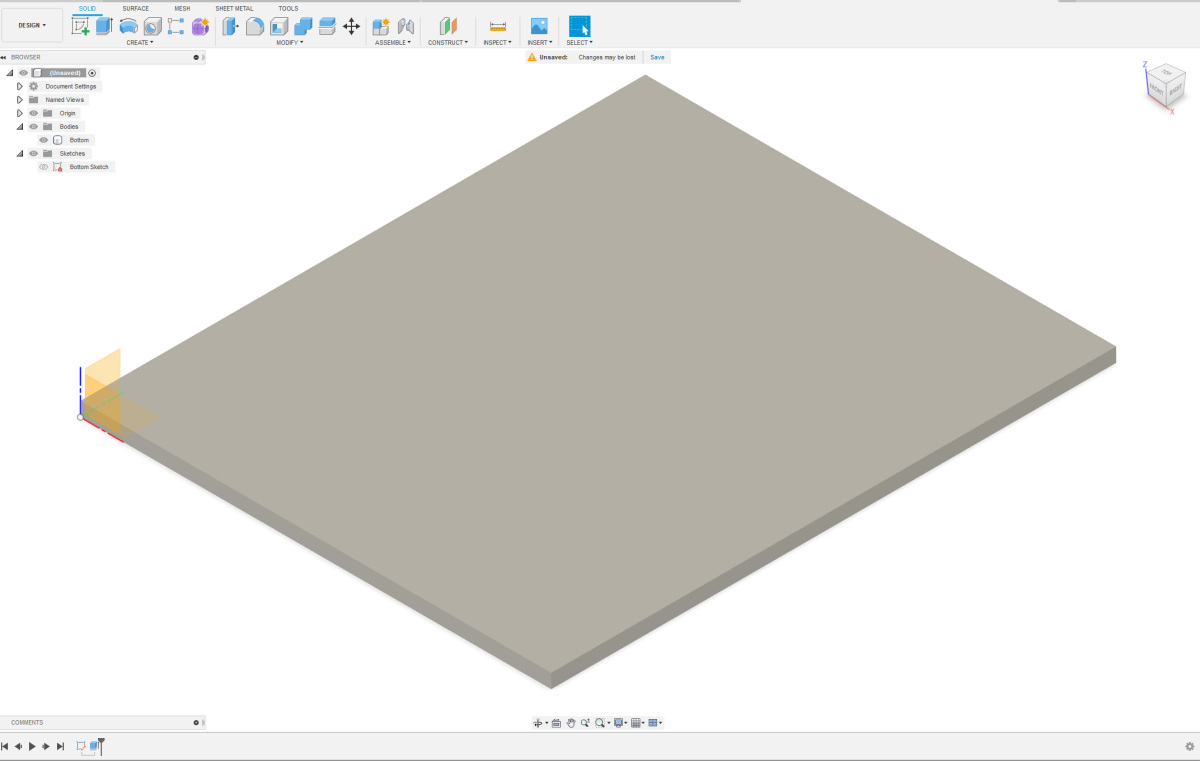 I rename my sketch to keep track of my design later on. Now, I'll extrude the sketch to create a plate. I extrude the plate upwards. Again, when extruding, I fill in a parameter, the Thickness. If I want to use thicker or thinner plates later, I can easily adjust my design. The body that is created now becomes the bottom of the box. I also give this body a logical name to keep track of it later. I rename my sketch to keep track of my design later on. Now, I'll extrude the sketch to create a plate. I extrude the plate upwards. Again, when extruding, I fill in a parameter, the Thickness. If I want to use thicker or thinner plates later, I can easily adjust my design. The body that is created now becomes the bottom of the box. I also give this body a logical name to keep track of it later. |
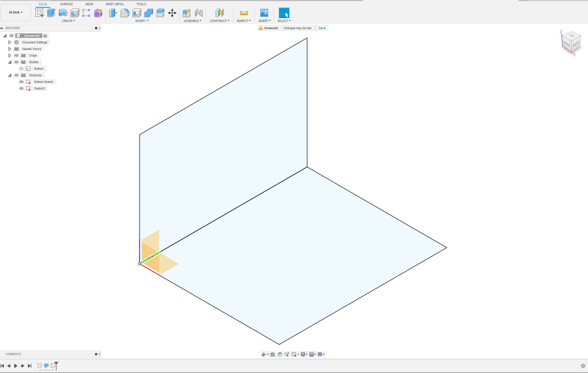 I will now create the sketch for the left side of the box. I make the bodies invisible and the sketches visible. On the blue/green plane or Z/Y plane in my case, I draw a square. I assign the sides the values of the appropriate parameters. Now, I need to connect these two sketches together. I use a coincident constraint to align the two front-left corner points. This sketch is also complete, and now I can give it a logical name. I will now create the sketch for the left side of the box. I make the bodies invisible and the sketches visible. On the blue/green plane or Z/Y plane in my case, I draw a square. I assign the sides the values of the appropriate parameters. Now, I need to connect these two sketches together. I use a coincident constraint to align the two front-left corner points. This sketch is also complete, and now I can give it a logical name. |
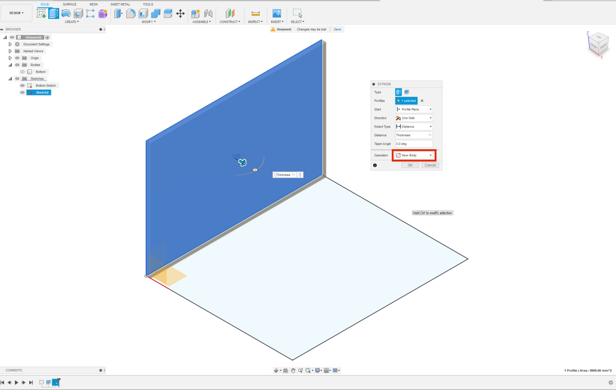 Just like with the bottom sketch, this sketch also needs to be extruded. I extrude the sketch to the right, as if forming the box. Once again, I use the parameter "Thickness". Make sure to extrude the sketch as a "New Body". If done correctly, you should now have 2 shapes under the "bodies" tab. Give your new body a logical name to maintain clarity. It's a good idea to save your design at this point. Just like with the bottom sketch, this sketch also needs to be extruded. I extrude the sketch to the right, as if forming the box. Once again, I use the parameter "Thickness". Make sure to extrude the sketch as a "New Body". If done correctly, you should now have 2 shapes under the "bodies" tab. Give your new body a logical name to maintain clarity. It's a good idea to save your design at this point. |
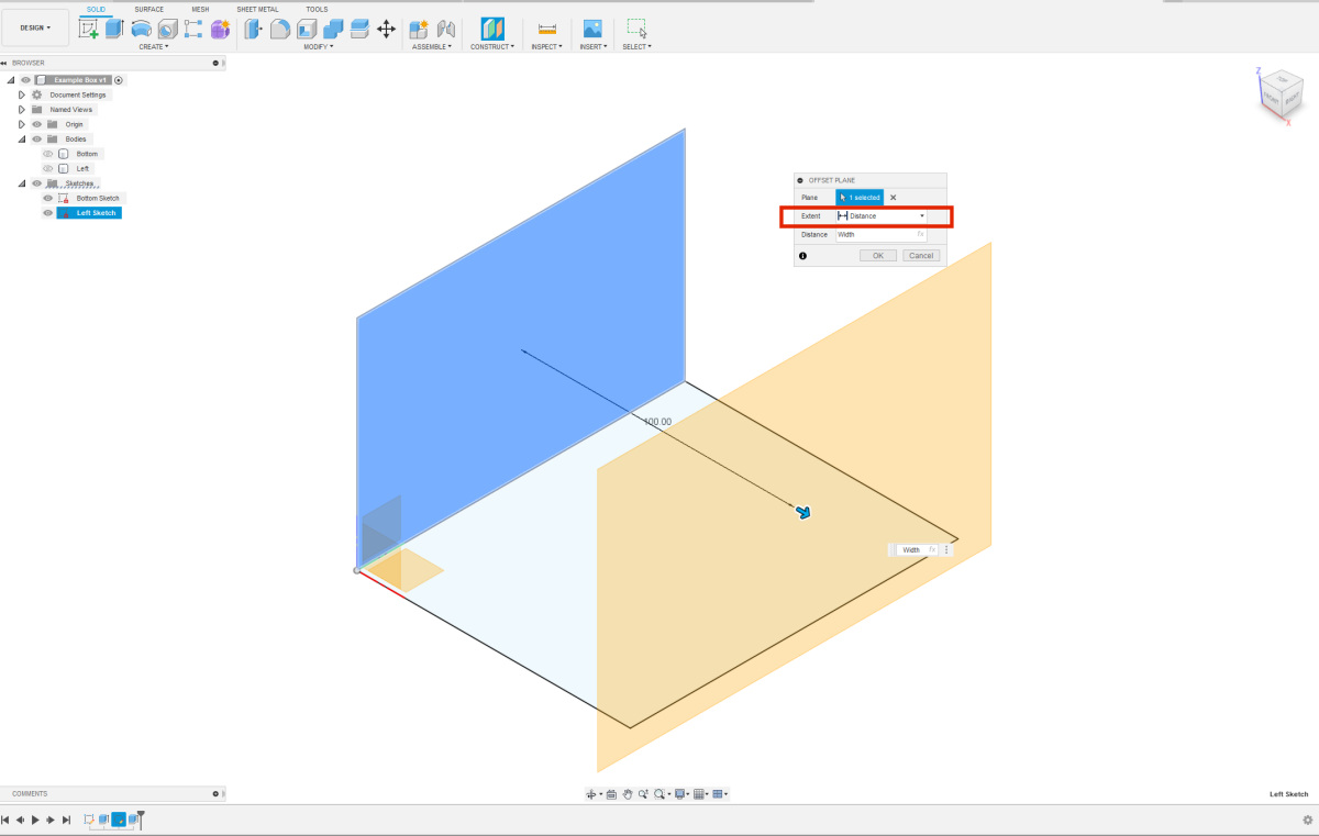 To design such a simple box, we could make a copy of the body on the left side and use it. However, for this guide, we will give each side its own sketch. To create the right side, we need to construct an offset plane. You can find offset planes under the "Construct" option in the menu at the top. Select the sketch of the left side for the plane, ensure that "Extent" is set to "Distance", and input the "Width" as the distance. To design such a simple box, we could make a copy of the body on the left side and use it. However, for this guide, we will give each side its own sketch. To create the right side, we need to construct an offset plane. You can find offset planes under the "Construct" option in the menu at the top. Select the sketch of the left side for the plane, ensure that "Extent" is set to "Distance", and input the "Width" as the distance. |
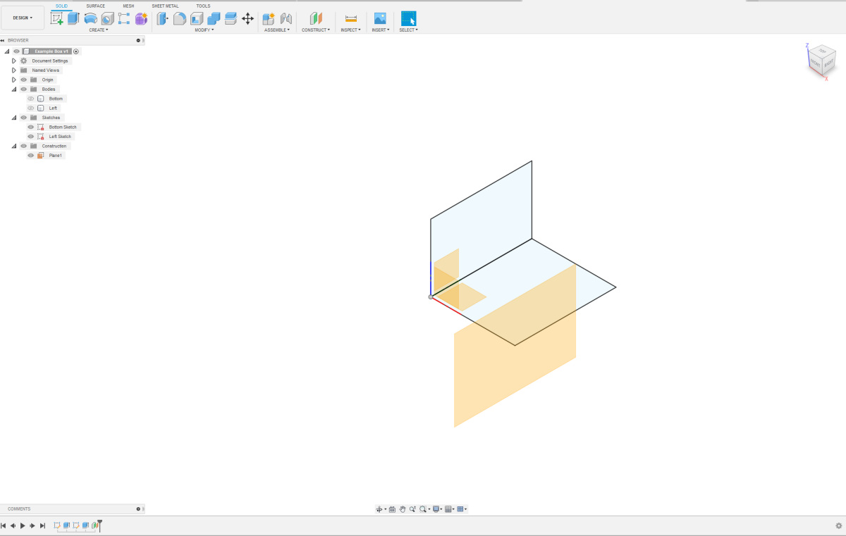 After clicking "OK," the layout may appear a bit odd, but don't worry, we'll fix it. Give your offset plane a logical name, then right-click on it and choose the option "Create Sketch." After clicking "OK," the layout may appear a bit odd, but don't worry, we'll fix it. Give your offset plane a logical name, then right-click on it and choose the option "Create Sketch." |
 In the sketch, draw another rectangle. For the sides, use the parameters again (Height for the height and Length for the horizontal length). Connect the bottom-left corner using a Coincident Constraint to the bottom-left corner of the existing sketches. Give your sketch a logical name again. In the sketch, draw another rectangle. For the sides, use the parameters again (Height for the height and Length for the horizontal length). Connect the bottom-left corner using a Coincident Constraint to the bottom-left corner of the existing sketches. Give your sketch a logical name again. |
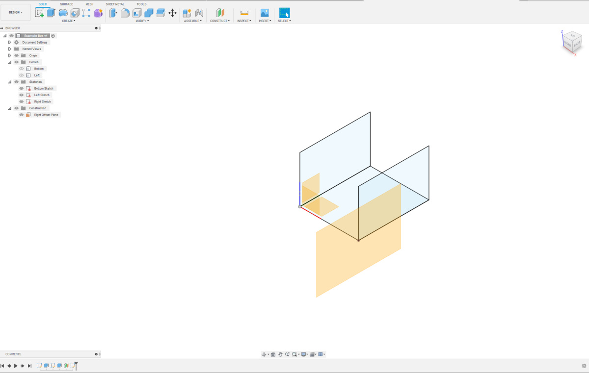
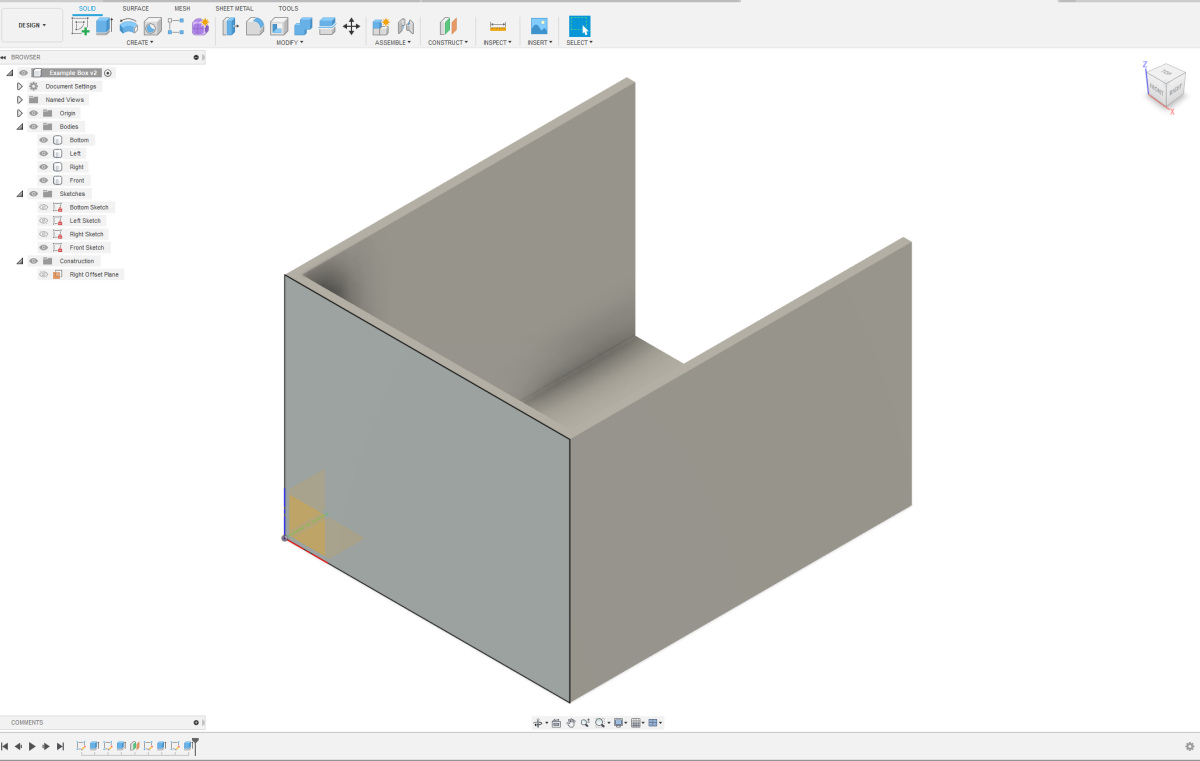
 Extrude the new sketch again, but this time towards the left. If the arrow points in the wrong direction, you can enter "-Thickness" to ensure that it extrudes in the correct direction. Make sure to select the option "New Body". You can make bodies, sketches, and construction planes visible and/or invisible to get a better overview. Give your body a logical name. If everything is done correctly, you should now have approximately the same shape as shown here, consisting of three parts. Extrude the new sketch again, but this time towards the left. If the arrow points in the wrong direction, you can enter "-Thickness" to ensure that it extrudes in the correct direction. Make sure to select the option "New Body". You can make bodies, sketches, and construction planes visible and/or invisible to get a better overview. Give your body a logical name. If everything is done correctly, you should now have approximately the same shape as shown here, consisting of three parts. |
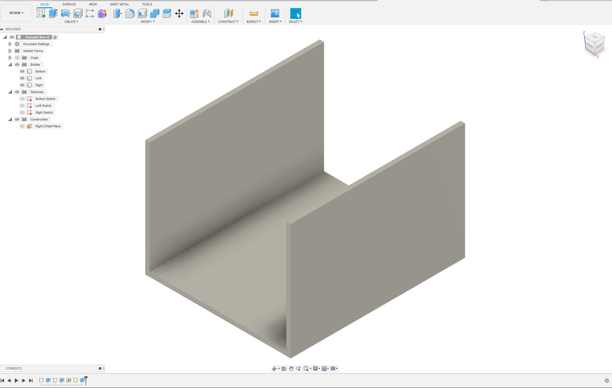
 Create the sketch for the front side in a similar manner, extrude the body for the front side, and give everything a logical name. Make sure to extrude the body in the direction of the box. The overall result should now resemble the image shown here. Create the sketch for the front side in a similar manner, extrude the body for the front side, and give everything a logical name. Make sure to extrude the body in the direction of the box. The overall result should now resemble the image shown here. |
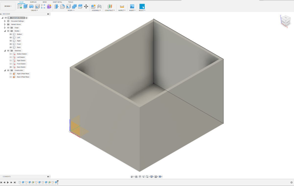 Create an Offset Plane relative to the sketch at the front side to enable the creation of the sketch at the back side. Extrude the body in the direction of the box. Give logical names to the offset plane, the sketch, and the extruded body. The overall result should now resemble the image shown here. Create an Offset Plane relative to the sketch at the front side to enable the creation of the sketch at the back side. Extrude the body in the direction of the box. Give logical names to the offset plane, the sketch, and the extruded body. The overall result should now resemble the image shown here. |
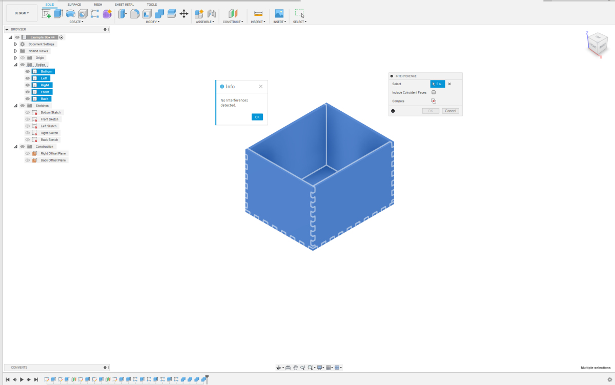
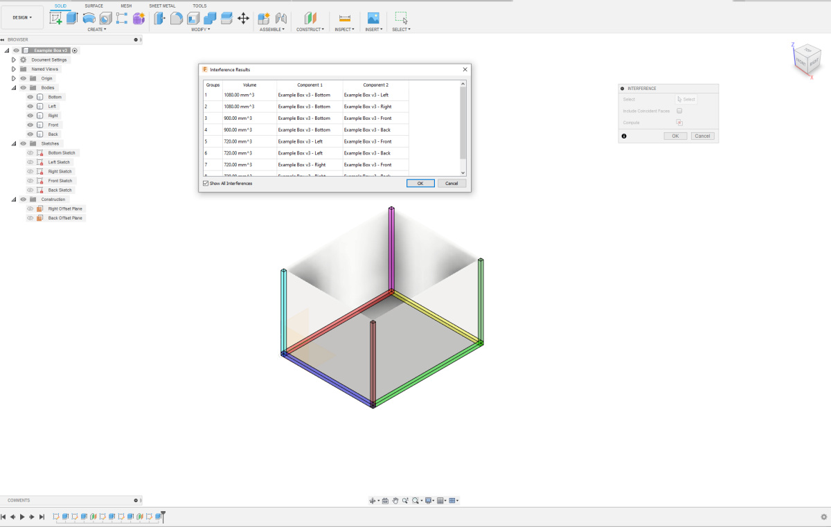 Now, the basic box is complete. However, it's not yet suitable for laser cutting and assembly because the parts overlap each other. You can easily observe this using the interference analysis tool in Fusion 360. This tool is very useful for checking if there are any overlapping parts in your design. You can find it under the "Inspect" option in the menu. Select your entire design, click on "Inspect" -> "Interference," and then click on "Compute." You'll now see all the parts that overlap each other highlighted in color. Now, the basic box is complete. However, it's not yet suitable for laser cutting and assembly because the parts overlap each other. You can easily observe this using the interference analysis tool in Fusion 360. This tool is very useful for checking if there are any overlapping parts in your design. You can find it under the "Inspect" option in the menu. Select your entire design, click on "Inspect" -> "Interference," and then click on "Compute." You'll now see all the parts that overlap each other highlighted in color. |
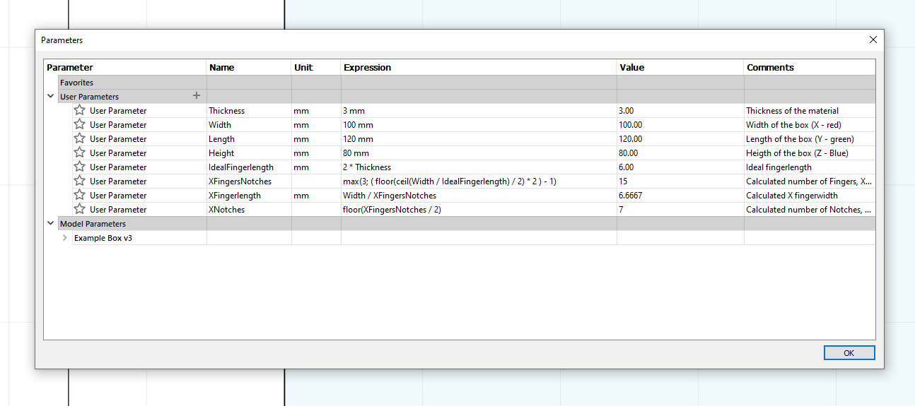 We are now going to create the fingers in the bottom. It works easier if you make all sketches, bodies, and planes invisible, except for the Bottom Sketch and the Bottom body. We need to calculate how large the fingers will be so that they are nicely proportionally distributed. There are a few formulas for this. We also always want an odd number of fingers and notches. If you start with a finger, you also end with one, and if you start with a notch, you also end with one. This will become clear in the images. The length of the fingers and notches are equal since a finger from another part of the design fits into a notch. As a rule of thumb, the length of the fingers and notches should be at least 2 times the thickness of your material. The width of the fingers and notches is equal to the thickness of your material. Together, this results in a number of formulas that you need to add to your parameters. We will start by making fingers on the X-axis of the bottom. For this, you need to add the following parameters. Note: XFingers has no unit. We are now going to create the fingers in the bottom. It works easier if you make all sketches, bodies, and planes invisible, except for the Bottom Sketch and the Bottom body. We need to calculate how large the fingers will be so that they are nicely proportionally distributed. There are a few formulas for this. We also always want an odd number of fingers and notches. If you start with a finger, you also end with one, and if you start with a notch, you also end with one. This will become clear in the images. The length of the fingers and notches are equal since a finger from another part of the design fits into a notch. As a rule of thumb, the length of the fingers and notches should be at least 2 times the thickness of your material. The width of the fingers and notches is equal to the thickness of your material. Together, this results in a number of formulas that you need to add to your parameters. We will start by making fingers on the X-axis of the bottom. For this, you need to add the following parameters. Note: XFingers has no unit.This is the ideal finger length: IdealFingerlength = 2 * Thickness The number of Fingers and Notches is calculated here: XFingersNotches = max(3; ( floor(ceil(Width / IdealFingerlength) / 2) * 2 ) - 1) Once we have calculated the number of Fingers and Notches, we can calculate the actual Finger length: XFingerlength = Width / XFingersNotches And the number of Notches: XNotches = floor(XFingersNotches / 2) The ideal finger length is the same for each direction; the other three calculations depend on the length in the respective direction and are therefore recalculated each time. |
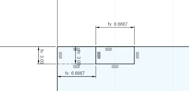 Now that we have added the parameters, let's actually create the notches and fingers. Draw a rectangle using construction lines with the width XFingerlength and height Thickness. Draw another rectangle with the same dimensions using regular lines. Fix the rectangle made with construction lines by applying a coincident constraint to the top-right corner of the bottom plate. Then, use a constraint to fix the rectangle with regular lines against the top and right side of the rectangle you just placed. Close your sketch. It's a good idea to save your design now. Now that we have added the parameters, let's actually create the notches and fingers. Draw a rectangle using construction lines with the width XFingerlength and height Thickness. Draw another rectangle with the same dimensions using regular lines. Fix the rectangle made with construction lines by applying a coincident constraint to the top-right corner of the bottom plate. Then, use a constraint to fix the rectangle with regular lines against the top and right side of the rectangle you just placed. Close your sketch. It's a good idea to save your design now. |
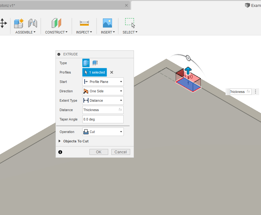 We are now going to create a hole, a notch, at the location of the rectangle constructed from regular lines. The rectangle constructed from construction lines is only meant to position the notch correctly. Select the Extrude option. For the profile, choose the rectangle that will become the notch. If you can't select it properly, you can temporarily make the Bottom body invisible. Once you have selected the rectangle, make the Bottom body visible again; otherwise, you won't be able to create a hole in it. Ensure that the direction of your extrude is upwards, through the plate. The distance is again Thickness, and the operation is Cut, as we are making a hole. We are now going to create a hole, a notch, at the location of the rectangle constructed from regular lines. The rectangle constructed from construction lines is only meant to position the notch correctly. Select the Extrude option. For the profile, choose the rectangle that will become the notch. If you can't select it properly, you can temporarily make the Bottom body invisible. Once you have selected the rectangle, make the Bottom body visible again; otherwise, you won't be able to create a hole in it. Ensure that the direction of your extrude is upwards, through the plate. The distance is again Thickness, and the operation is Cut, as we are making a hole. |
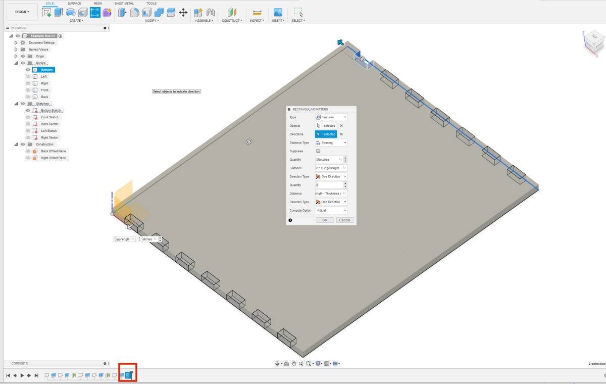 Now that we have one hole, we can create the holes across the entire X-axis and even on both sides of the bottom in one go. Select Rectangular Pattern. Choose Feature as the type, as we are repeating the creation of the hole, which is a feature. For the object, select the Extrude you just made from the bottom of the history bar; it's outlined in red in the image. The direction is the X-axis; click on the red axis in the origin of the sketch or the X-axis in your bottom sketch. Set the distance type to spacing, and the quantity to XNotches. The distance between 2 notches is 2 times the finger length, so 2X XFingerlength. Choose to let the pattern go in only one direction. Now you have filled in everything for one side. But we can immediately provide the opposite side with notches as well. So, the value for the second option for Quantity should be 2. The distance between the rows of notches is the Y-direction or the Length, but minus the thickness of the material. If it turns out that the notches are not drawn on the plate but on the wrong side of the first row, you need to put brackets around the formula for the Distance and add a minus sign before it. The formula then becomes (Length - Thickness). Here too, the direction type is One direction. Click "OK" to apply the settings. Now that we have one hole, we can create the holes across the entire X-axis and even on both sides of the bottom in one go. Select Rectangular Pattern. Choose Feature as the type, as we are repeating the creation of the hole, which is a feature. For the object, select the Extrude you just made from the bottom of the history bar; it's outlined in red in the image. The direction is the X-axis; click on the red axis in the origin of the sketch or the X-axis in your bottom sketch. Set the distance type to spacing, and the quantity to XNotches. The distance between 2 notches is 2 times the finger length, so 2X XFingerlength. Choose to let the pattern go in only one direction. Now you have filled in everything for one side. But we can immediately provide the opposite side with notches as well. So, the value for the second option for Quantity should be 2. The distance between the rows of notches is the Y-direction or the Length, but minus the thickness of the material. If it turns out that the notches are not drawn on the plate but on the wrong side of the first row, you need to put brackets around the formula for the Distance and add a minus sign before it. The formula then becomes (Length - Thickness). Here too, the direction type is One direction. Click "OK" to apply the settings. |
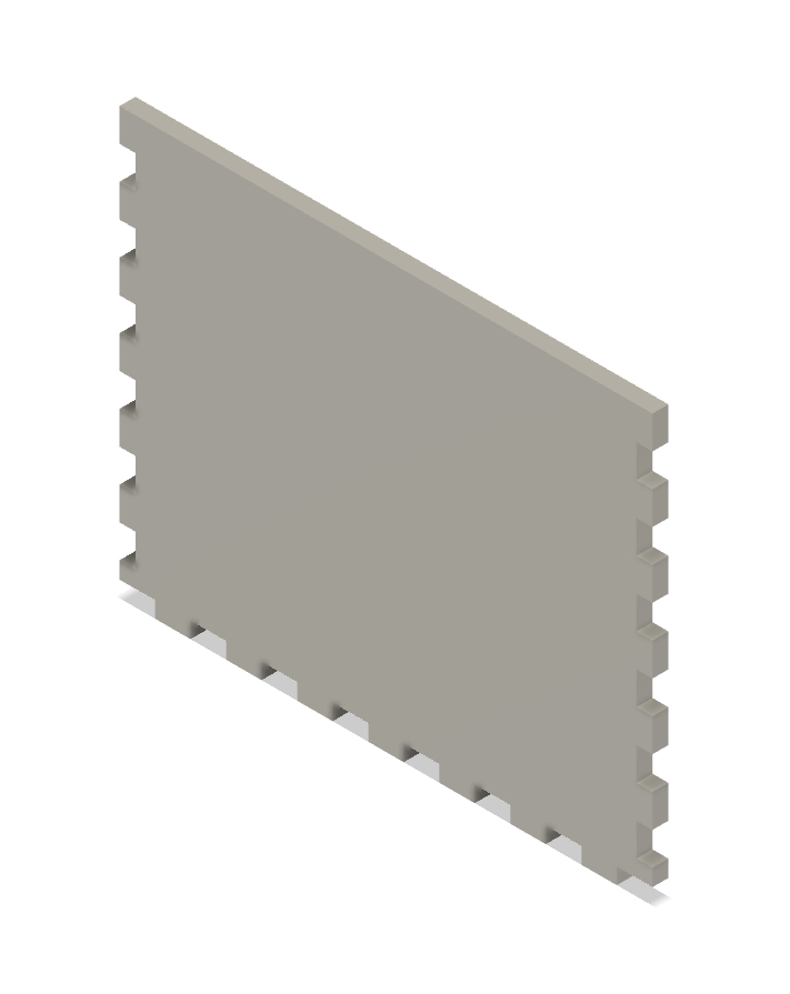
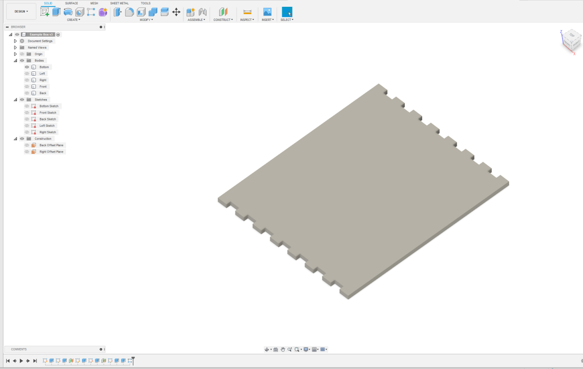 If you've done everything correctly, your bottom plate should now look like the one shown here. You now have notches and fingers on 2 sides. We're going to repeat the same trick for the Y direction. For that, you need to add the following parameters: If you've done everything correctly, your bottom plate should now look like the one shown here. You now have notches and fingers on 2 sides. We're going to repeat the same trick for the Y direction. For that, you need to add the following parameters:YFingersNotches = max(3; ( floor(ceil(Length / IdealFingerlength) / 2) * 2 ) - 1) YFingerlength = Length / YFingersNotches YNotches = floor(YFingersNotches / 2) |
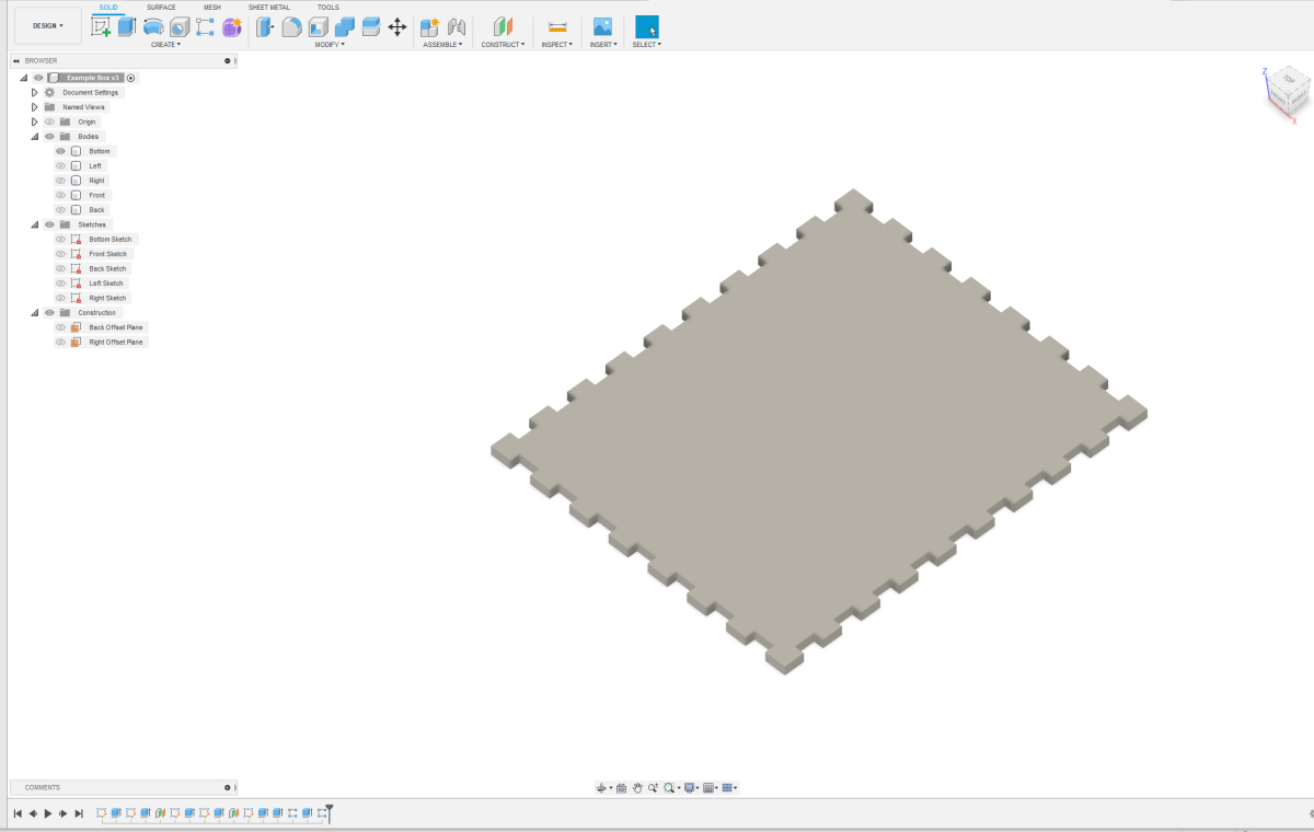 Create another notch in the Y direction. It doesn't matter which corner you choose to fix your first rectangles in the sketch. Once you've created the first hole, you can use rectangular pattern to create the other notches again. If you've done everything correctly, your bottom plate should now look like the one shown here. We're making progress. It's a good idea to save your design again. Create another notch in the Y direction. It doesn't matter which corner you choose to fix your first rectangles in the sketch. Once you've created the first hole, you can use rectangular pattern to create the other notches again. If you've done everything correctly, your bottom plate should now look like the one shown here. We're making progress. It's a good idea to save your design again. |
 Now that we've finished the bottom plate, let's create notches on the left and right sides of both the front and back. For this, you'll need a few more parameters. Add the following parameters: Now that we've finished the bottom plate, let's create notches on the left and right sides of both the front and back. For this, you'll need a few more parameters. Add the following parameters:ZFingersNotches = max(3; ( floor(ceil(Height / IdealFingerlength) / 2) * 2 ) - 1) ZFingerlength = Height / ZFingersNotches ZNotches = floor(ZFingersNotches / 2) ou should now have the parameters and formulas as shown in the image. |
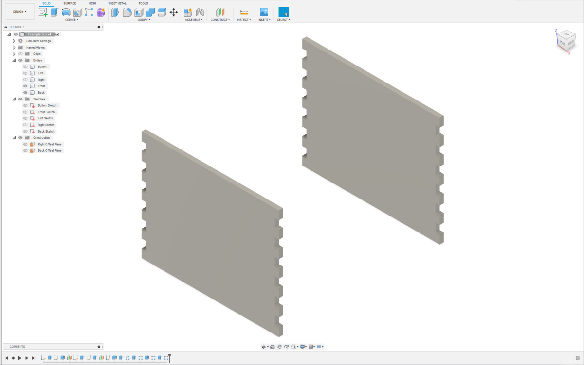 It's possible that when filling in the values for the circular pattern, you may need to swap the values for the first and second directions. Look closely at your image when filling this in, and it should become clear. If everything went well, your front and back should look like the image next to this one. Now it's time for the final steps. It's possible that when filling in the values for the circular pattern, you may need to swap the values for the first and second directions. Look closely at your image when filling this in, and it should become clear. If everything went well, your front and back should look like the image next to this one. Now it's time for the final steps. |
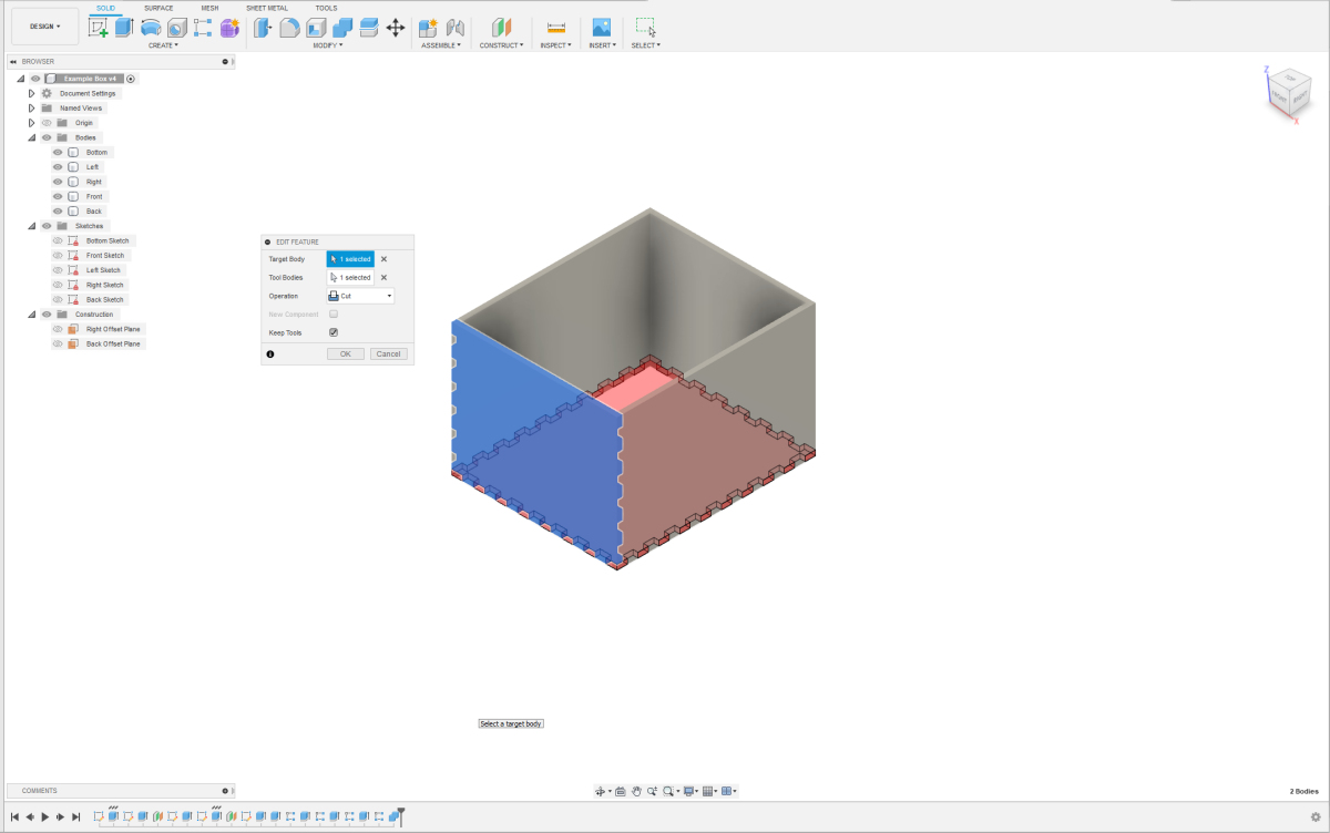 For the final steps, we will use the combine option. By combining a panel that already has notches with an overlapping panel, we will make them fit perfectly and remove any overlap. We start by making notches in the front panel. For the final steps, we will use the combine option. By combining a panel that already has notches with an overlapping panel, we will make them fit perfectly and remove any overlap. We start by making notches in the front panel. Select the Modify Option: - Choose the "Modify" option. - Select the front panel as the target body. - Select the bottom panel as the tool body. Set the Operation: - The operation is set to "Cut" because we are creating holes in the front panel. - We use the shape already in the bottom panel to position these holes exactly. - We still need the bottom panel, the bottom of the box, so check "Keep Tools." Apply the Changes: - Click "OK" to apply the changes. By following these steps, the notches will be created in the front panel, perfectly aligned with the bottom panel. This method ensures a precise fit without any overlaps. |
 If done correctly, your front panel should now look like the photo shown here. If this is not clearly visible, make the other components invisible. We will use the same method to create fingers and notches in the back panel. If done correctly, your front panel should now look like the photo shown here. If this is not clearly visible, make the other components invisible. We will use the same method to create fingers and notches in the back panel. |
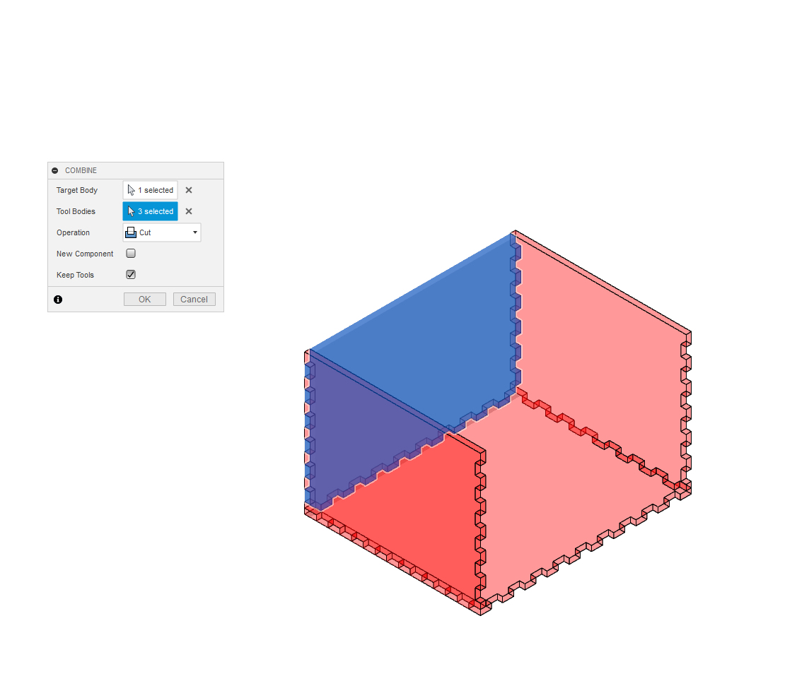 Now the bottom, front, and back are complete. We only need to add notches and fingers to both sides. This process is similar to the previous steps. However, we will now take advantage of the ability to select multiple tool bodies at once. For the left side, select bottom, front, and back as tool bodies. The rest of the options remain the same. Now the bottom, front, and back are complete. We only need to add notches and fingers to both sides. This process is similar to the previous steps. However, we will now take advantage of the ability to select multiple tool bodies at once. For the left side, select bottom, front, and back as tool bodies. The rest of the options remain the same. |
 We apply the same trick for the right side. If we check for interference again, we will see that there are no more overlaps in our design. We now have a basic box with finger joints. You can export this design as a .DXF file with kerf compensation. Afterwards, you can edit it in a software package like CorelDRAW, Illustrator, or Inkscape to add engravings, for example. You can read about how to apply kerf compensation in another article. We apply the same trick for the right side. If we check for interference again, we will see that there are no more overlaps in our design. We now have a basic box with finger joints. You can export this design as a .DXF file with kerf compensation. Afterwards, you can edit it in a software package like CorelDRAW, Illustrator, or Inkscape to add engravings, for example. You can read about how to apply kerf compensation in another article. |
 If you want to use this basic box for something else but the dimensions are not right, you can easily adjust this in the parameters. Fusion will recalculate everything for you. It's very handy to have such a standard box design. If you want to use this basic box for something else but the dimensions are not right, you can easily adjust this in the parameters. Fusion will recalculate everything for you. It's very handy to have such a standard box design. |