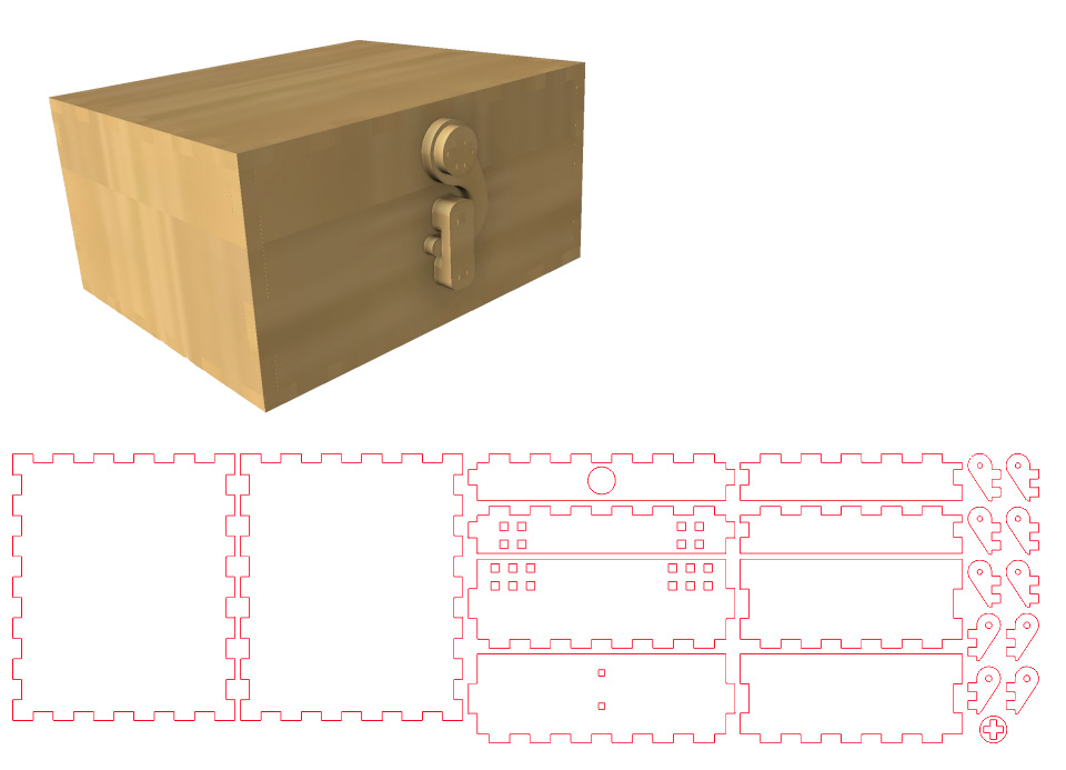
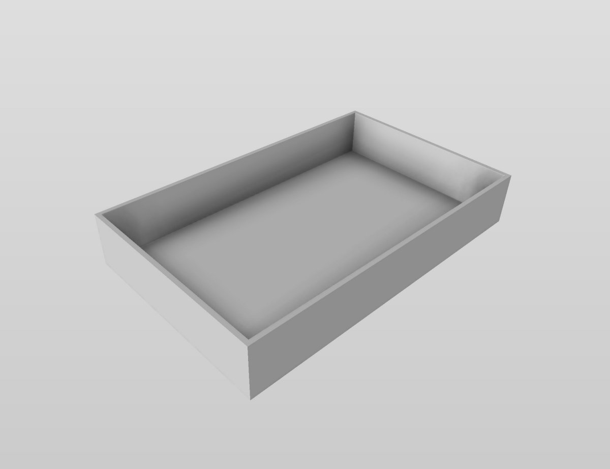
| I design my boxes in Fusion 360. When designing, I take into account that I'm working with sheet material. Therefore, I build my design from the beginning using sheets rather than volumes. This makes it easier to actually create the box later on. In this guide, I'll show you how to make a simple box without a lid using finger joints. I assume you have some basic knowledge of Fusion for this explanation. |
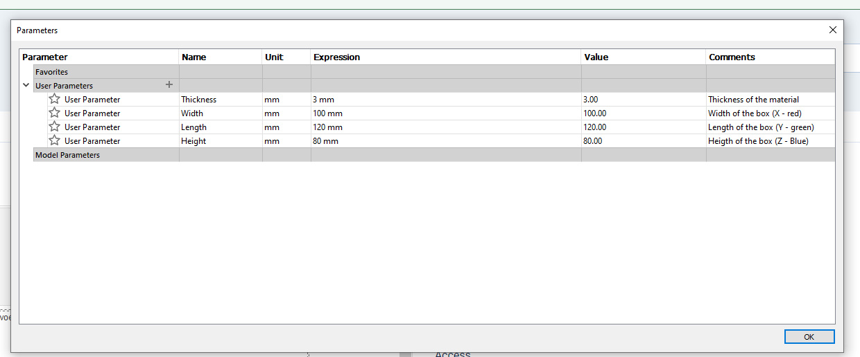
Before I start my design, I'll specify some basic parameters (Modify - Change Parameters). I'll specify the material thickness (Thickness) and the outer dimensions of the box. Now I can use these parameters consistently. If I need to adjust the box later on, I can easily modify the values in the parameter table.
|
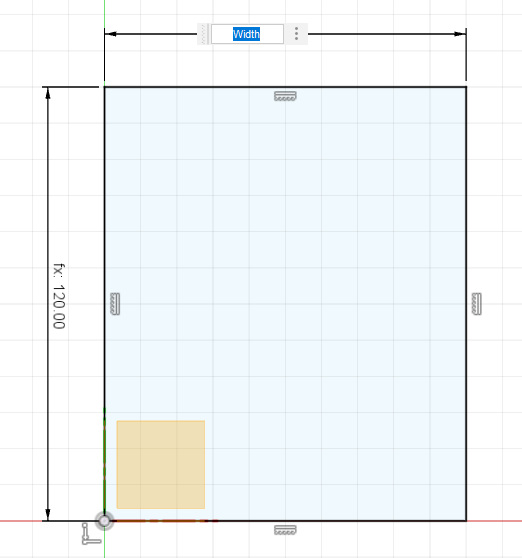
| Now that I've specified these values, I can use them in the sketch. I'll start by creating a sketch for the bottom plate of the box. This is a simple rectangle. Instead of specifying 100mm for the width, I'll use the parameter Width. Similarly, for the length, I'll use a parameter, Length, instead of a specific value. |
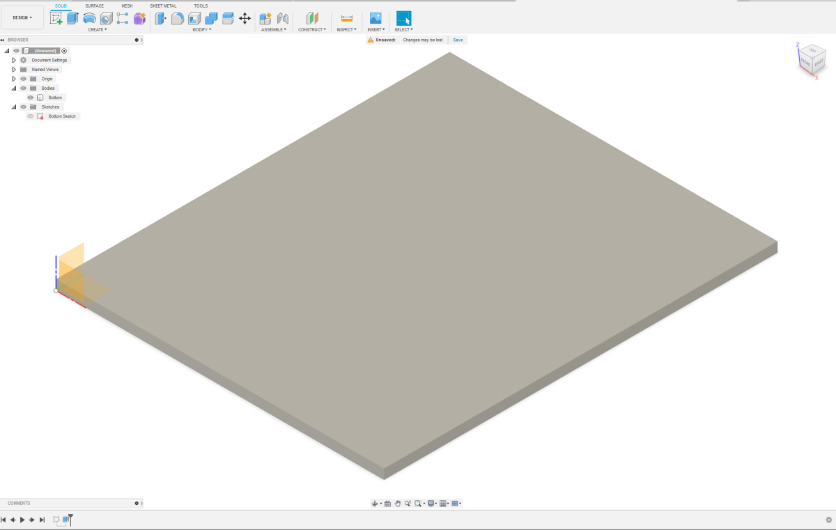
I rename my sketch to keep track of my design later on. Now, I'll extrude the sketch to create a plate. I extrude the plate upwards. Again, when extruding, I fill in a parameter, the Thickness. If I want to use thicker or thinner plates later, I can easily adjust my design. The body that is created now becomes the bottom of the box. I also give this body a logical name to keep track of it later.
|
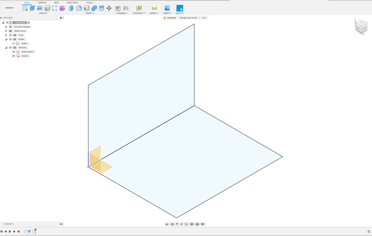
I will now create the sketch for the left side of the box. I make the bodies invisible and the sketches visible. On the blue/green plane or Z/Y plane in my case, I draw a square. I assign the sides the values of the appropriate parameters. Now, I need to connect these two sketches together. I use a coincident constraint to align the two front-left corner points. This sketch is also complete, and now I can give it a logical name.
|
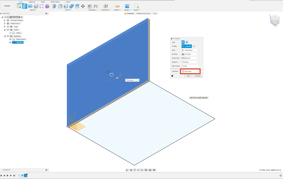
| Just like with the bottom sketch, this sketch also needs to be extruded. I extrude the sketch to the right, as if forming the box. Once again, I use the parameter "Thickness". Make sure to extrude the sketch as a "New Body". If done correctly, you should now have 2 shapes under the "bodies" tab. Give your new body a logical name to maintain clarity. It's a good idea to save your design at this point. |
