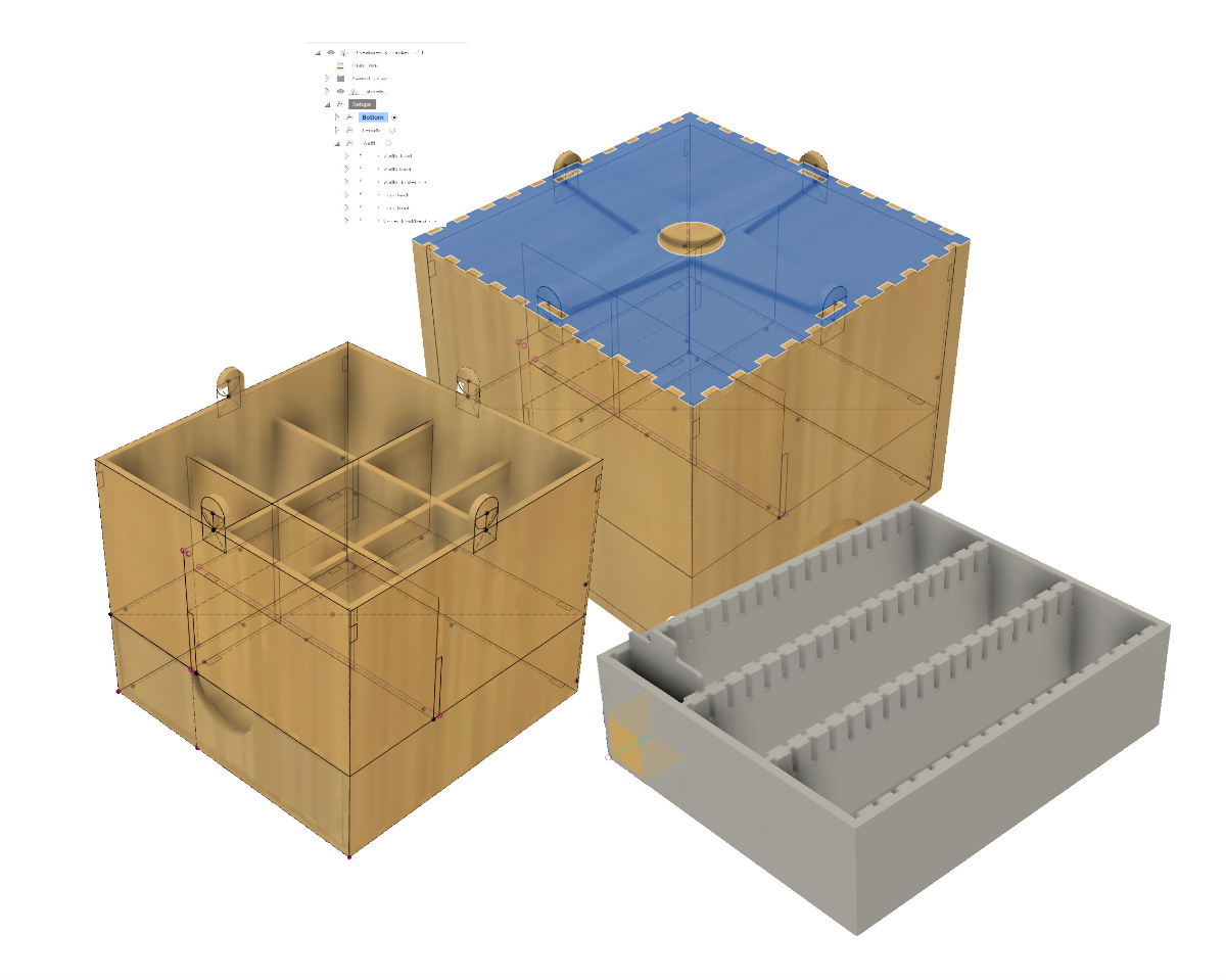
Something important for my boxes is kerf compensation. When I design a box and cut out the various parts with the laser cutter, the laser removes a small amount of material. The width of the cut line depends on the laser, the material, its thickness, and the power I use. The amount of material removed can be determined experimentally. In my case, for example, the thickness of the line removed from 3mm birch plywood is 0.16 mm. If I don't account for this removed material, the parts of my box fit a bit loosely together. This isn't necessarily a problem; with enough glue and some clamps, the box can still be assembled fine. However, if I compensate for the kerf, I can practically assemble my boxes without glue, as the shapes fit together perfectly. The photo next to this text clearly shows the kerf.
|
| To work with kerf compensation in Fusion 360, you need to set up a few things. Additionally, once your design is complete, you'll also need to configure the manufacturing part of your design. To set everything up in Fusion 360, you'll need the two files from this archive. We'll start by enabling the Cloud Libraries. You can do this in "Preferences" and then under "General" in the "Manufacture" section. |
| Once you've done this, you should see several folders appear on the left side of your menu under "Assets." |
| In the COMPosts folder, we're going to upload the file dxf.cps. This file is located in the .zip archive that you downloaded at the beginning of this guide. This file enables you to export the entire design as a .dxf file in one go, with kerf compensation already applied to the various profiles. |
| The other file from the archive, Library.json, needs to be uploaded to the CAMTools folder. With this file, you'll be able to create various options for different kerf compensations. Now that you have all the necessary files, we need to configure a few things in the Manufacturing section of Fusion. |

")
")

 Fusion 360 is fantastic 3D design software. As a hobbyist, you can also request a free license. You can renew it annually. Some features may not be available, but it's sufficient for the few boxes I occasionally design.
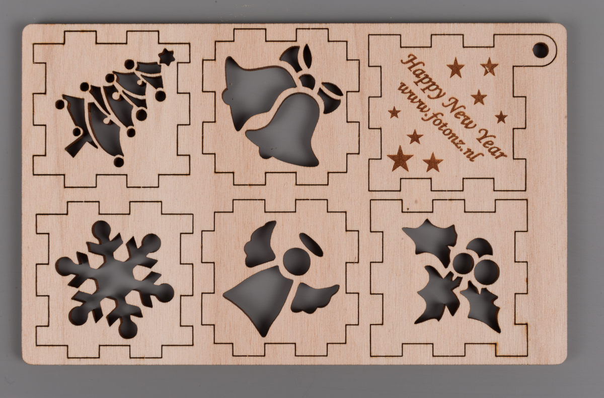 Something important for my boxes is kerf compensation. When I design a box and cut out the various parts with the laser cutter, the laser removes a small amount of material. The width of the cut line depends on the laser, the material, its thickness, and the power I use. The amount of material removed can be determined experimentally. In my case, for example, the thickness of the line removed from 3mm birch plywood is 0.16 mm. If I don't account for this removed material, the parts of my box fit a bit loosely together. This isn't necessarily a problem; with enough glue and some clamps, the box can still be assembled fine. However, if I compensate for the kerf, I can practically assemble my boxes without glue, as the shapes fit together perfectly. The photo next to this text clearly shows the kerf.
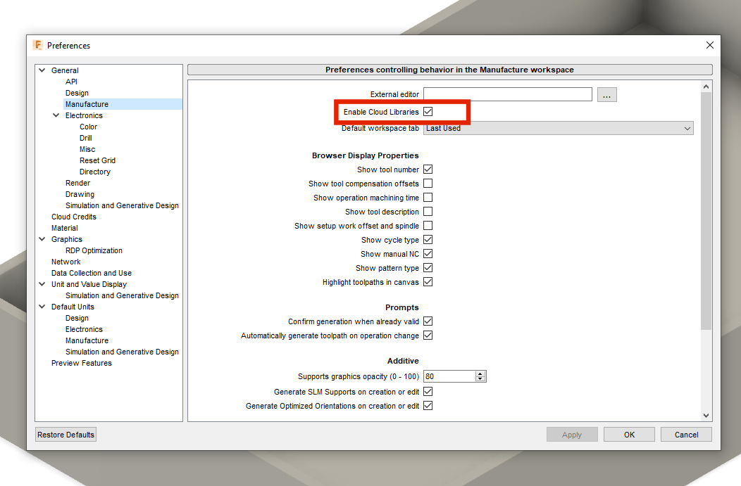 To work with kerf compensation in Fusion 360, you need to set up a few things. Additionally, once your design is complete, you'll also need to configure the manufacturing part of your design. To set everything up in Fusion 360, you'll need the two files from this archive. We'll start by enabling the Cloud Libraries. You can do this in "Preferences" and then under "General" in the "Manufacture" section.
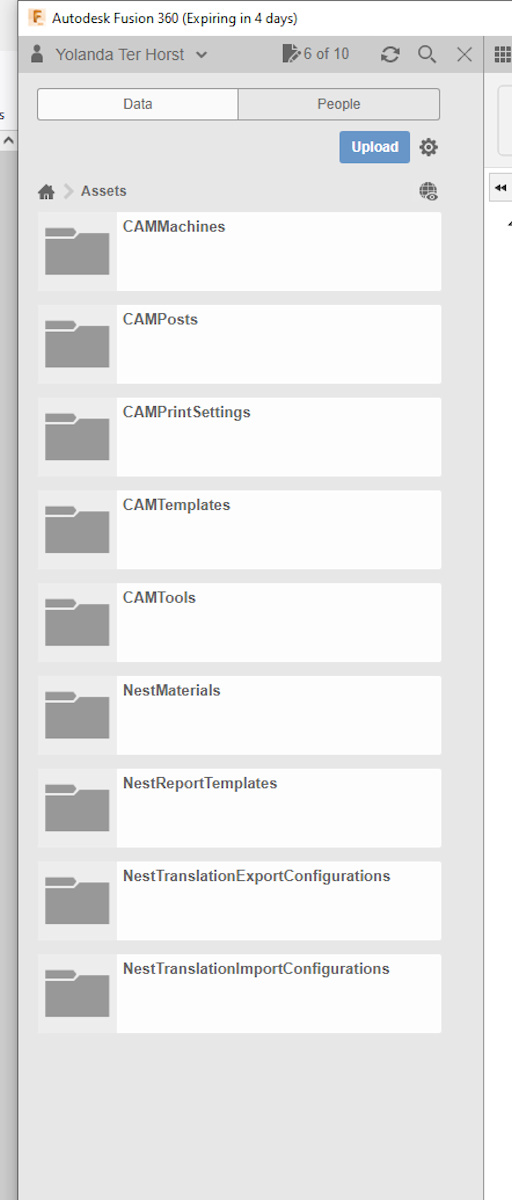 Once you've done this, you should see several folders appear on the left side of your menu under "Assets."
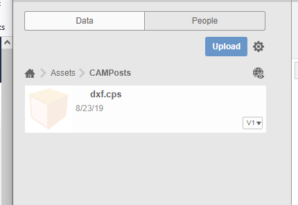 In the COMPosts folder, we're going to upload the file dxf.cps. This file is located in the .zip archive that you downloaded at the beginning of this guide. This file enables you to export the entire design as a .dxf file in one go, with kerf compensation already applied to the various profiles.
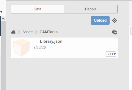 The other file from the archive, Library.json, needs to be uploaded to the CAMTools folder. With this file, you'll be able to create various options for different kerf compensations. Now that you have all the necessary files, we need to configure a few things in the Manufacturing section of Fusion.