
")
")

 Fusion 360 is fantastic 3D design software. As a hobbyist, you can also request a free license. You can renew it annually. Some features may not be available, but it's sufficient for the few boxes I occasionally design. Fusion 360 is fantastic 3D design software. As a hobbyist, you can also request a free license. You can renew it annually. Some features may not be available, but it's sufficient for the few boxes I occasionally design. |
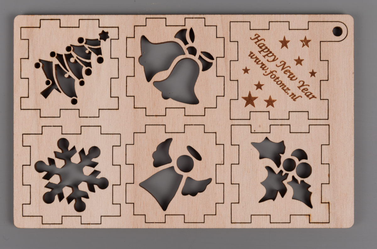 Something important for my boxes is kerf compensation. When I design a box and cut out the various parts with the laser cutter, the laser removes a small amount of material. The width of the cut line depends on the laser, the material, its thickness, and the power I use. The amount of material removed can be determined experimentally. In my case, for example, the thickness of the line removed from 3mm birch plywood is 0.16 mm. If I don't account for this removed material, the parts of my box fit a bit loosely together. This isn't necessarily a problem; with enough glue and some clamps, the box can still be assembled fine. However, if I compensate for the kerf, I can practically assemble my boxes without glue, as the shapes fit together perfectly. The photo next to this text clearly shows the kerf. Something important for my boxes is kerf compensation. When I design a box and cut out the various parts with the laser cutter, the laser removes a small amount of material. The width of the cut line depends on the laser, the material, its thickness, and the power I use. The amount of material removed can be determined experimentally. In my case, for example, the thickness of the line removed from 3mm birch plywood is 0.16 mm. If I don't account for this removed material, the parts of my box fit a bit loosely together. This isn't necessarily a problem; with enough glue and some clamps, the box can still be assembled fine. However, if I compensate for the kerf, I can practically assemble my boxes without glue, as the shapes fit together perfectly. The photo next to this text clearly shows the kerf. |
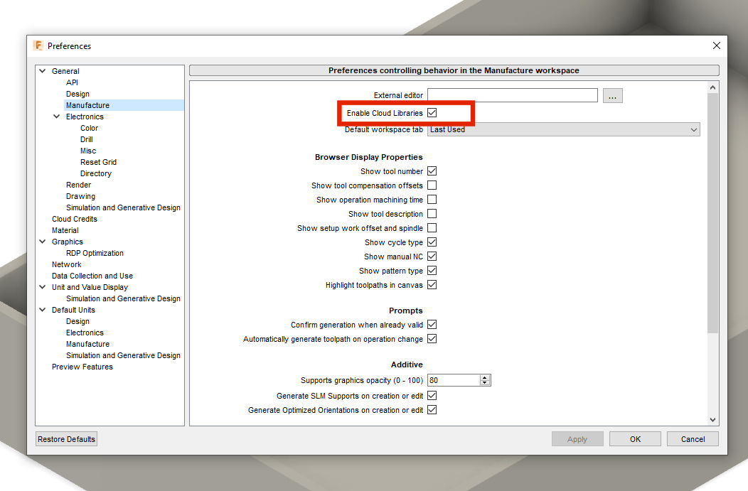 To work with kerf compensation in Fusion 360, you need to set up a few things. Additionally, once your design is complete, you'll also need to configure the manufacturing part of your design. To set everything up in Fusion 360, you'll need the two files from this archive. We'll start by enabling the Cloud Libraries. You can do this in "Preferences" and then under "General" in the "Manufacture" section. To work with kerf compensation in Fusion 360, you need to set up a few things. Additionally, once your design is complete, you'll also need to configure the manufacturing part of your design. To set everything up in Fusion 360, you'll need the two files from this archive. We'll start by enabling the Cloud Libraries. You can do this in "Preferences" and then under "General" in the "Manufacture" section. |
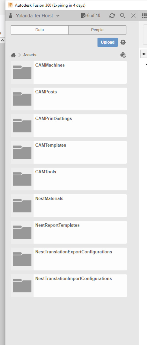 Once you've done this, you should see several folders appear on the left side of your menu under "Assets." Once you've done this, you should see several folders appear on the left side of your menu under "Assets." |
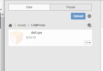 In the COMPosts folder, we're going to upload the file dxf.cps. This file is located in the .zip archive that you downloaded at the beginning of this guide. This file enables you to export the entire design as a .dxf file in one go, with kerf compensation already applied to the various profiles. In the COMPosts folder, we're going to upload the file dxf.cps. This file is located in the .zip archive that you downloaded at the beginning of this guide. This file enables you to export the entire design as a .dxf file in one go, with kerf compensation already applied to the various profiles. |
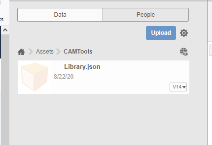 The other file from the archive, Library.json, needs to be uploaded to the CAMTools folder. With this file, you'll be able to create various options for different kerf compensations. Now that you have all the necessary files, we need to configure a few things in the Manufacturing section of Fusion. The other file from the archive, Library.json, needs to be uploaded to the CAMTools folder. With this file, you'll be able to create various options for different kerf compensations. Now that you have all the necessary files, we need to configure a few things in the Manufacturing section of Fusion. |
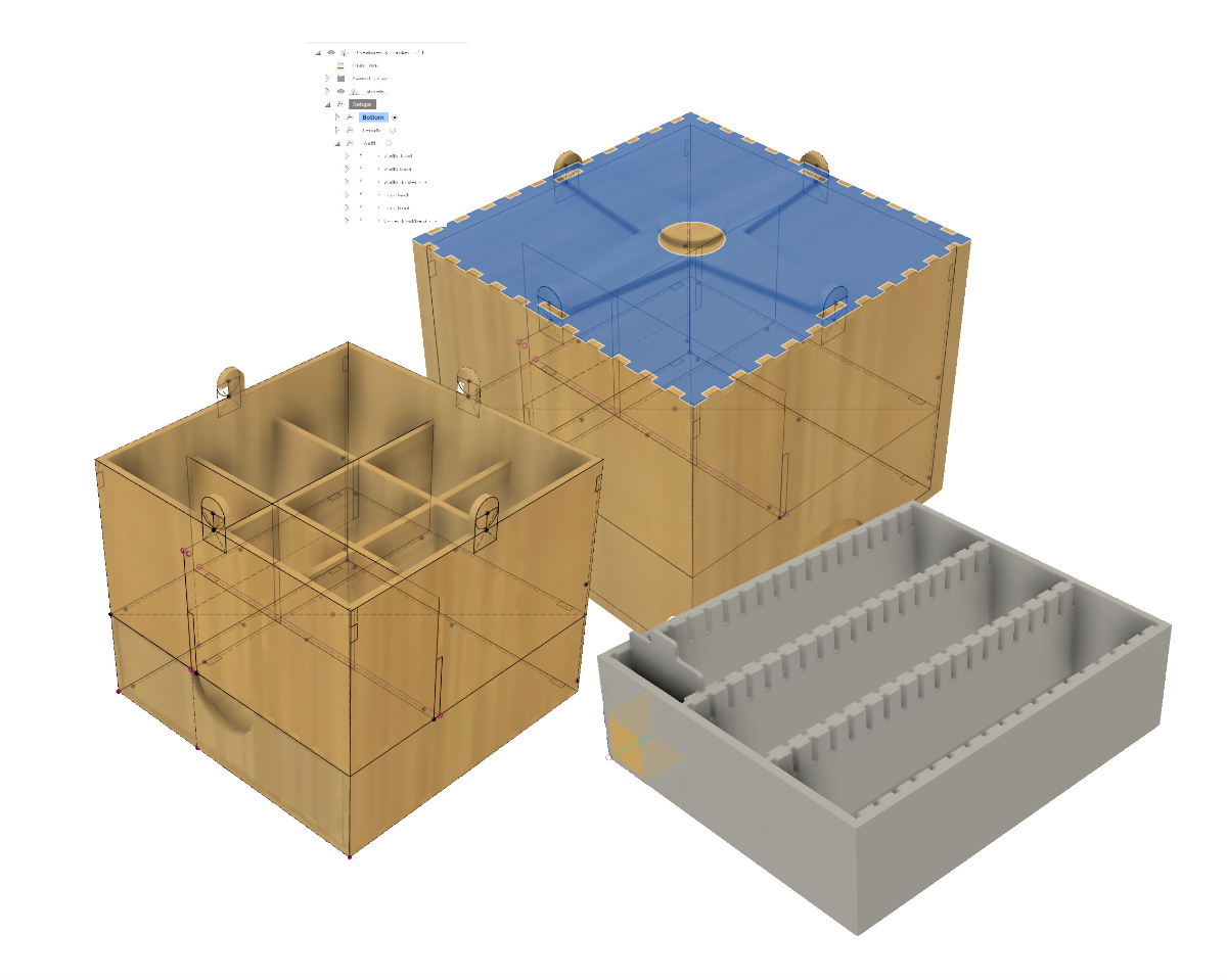
 In Fusion 360, I've designed a simple box with finger joints made from sheet material. The various parts are connected with finger joints. I'd like to laser-cut this from 3mm birch plywood. In the design, I've already taken into account the thickness of the material. However, I can only adjust the kerf compensation in the Manufacturing section. In Fusion 360, I've designed a simple box with finger joints made from sheet material. The various parts are connected with finger joints. I'd like to laser-cut this from 3mm birch plywood. In the design, I've already taken into account the thickness of the material. However, I can only adjust the kerf compensation in the Manufacturing section. |
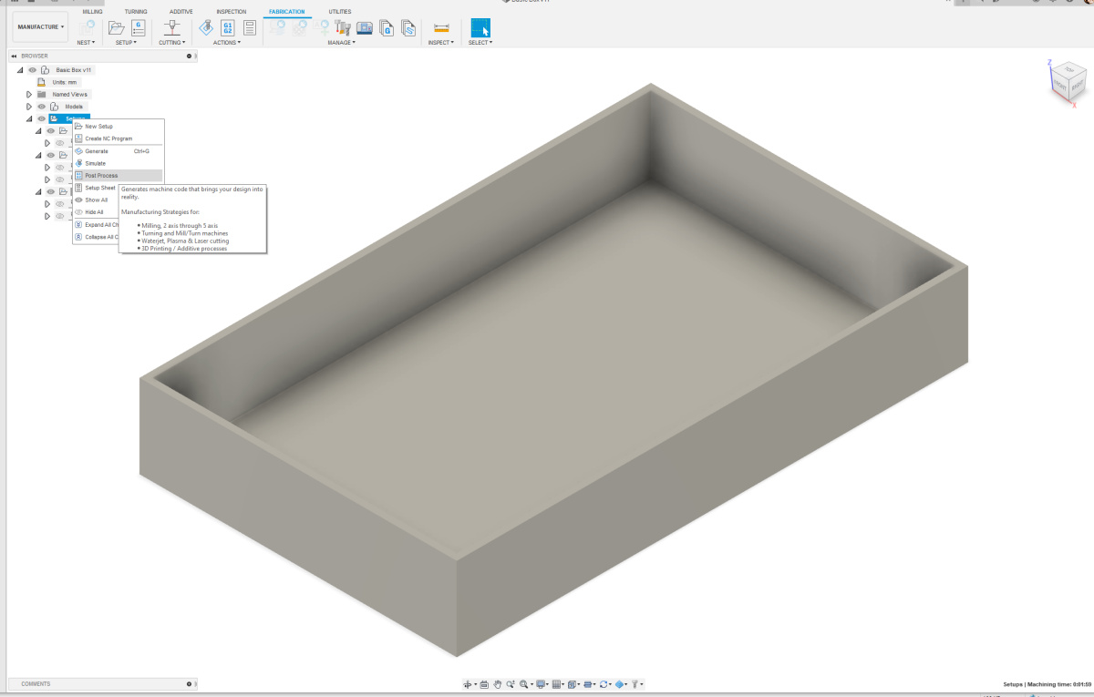 In the image next to this, you can see that the three setups Top, Front, and Side have already been created. Under each setup, the correct profiles have also been made. If I right-click now, I can select the Post Process option. Here, something still needs to be set up so that everything works correctly. In the image next to this, you can see that the three setups Top, Front, and Side have already been created. Under each setup, the correct profiles have also been made. If I right-click now, I can select the Post Process option. Here, something still needs to be set up so that everything works correctly. |
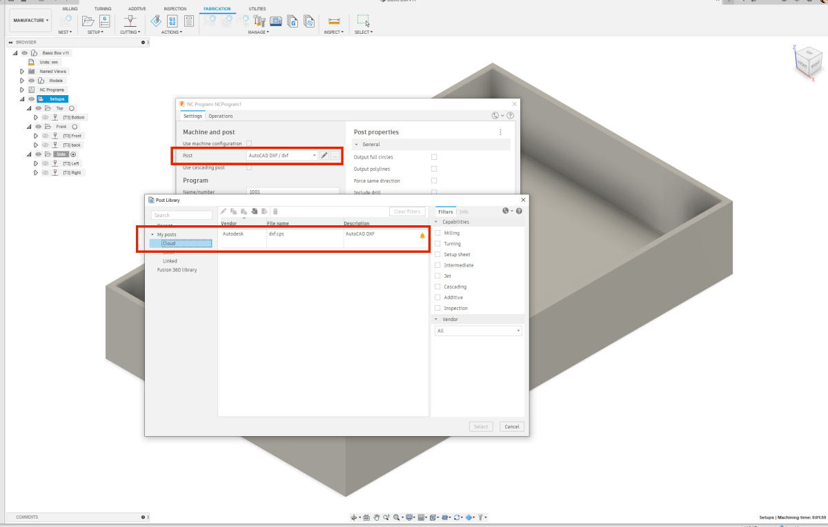 In the Settings tab, under Post, the file dxf.cps needs to be selected. Click on the three dots next to the pencil icon to select this file. You've just uploaded the file to the Cloud. In the Settings tab, under Post, the file dxf.cps needs to be selected. Click on the three dots next to the pencil icon to select this file. You've just uploaded the file to the Cloud. |
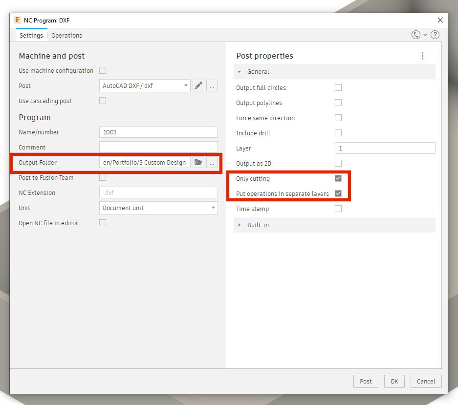 In addition to the post-processor, the output folder can also be set here. On the right side, two options need to be turned on: "Only Cutting" and "Put operations in separate layers." If the options are not visible, you need to click on the three dots in the upper right corner to make them visible.. In addition to the post-processor, the output folder can also be set here. On the right side, two options need to be turned on: "Only Cutting" and "Put operations in separate layers." If the options are not visible, you need to click on the three dots in the upper right corner to make them visible.. |
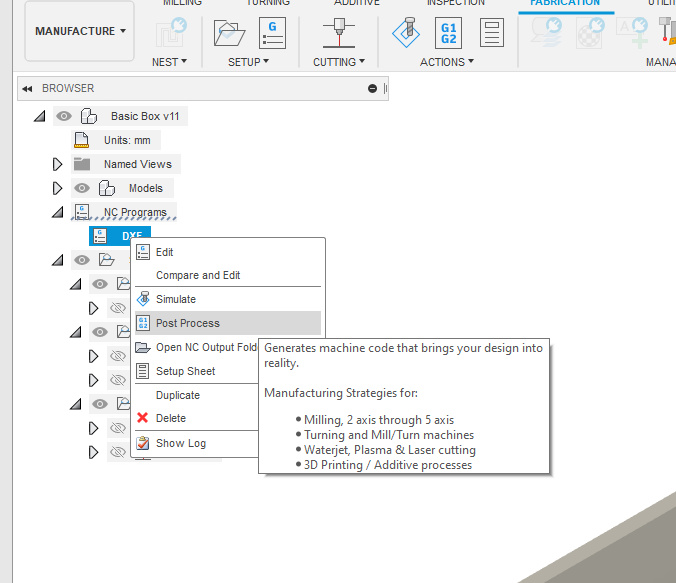 The recently set NC program is now visible under NC programs. I renamed it to DXF. By right-clicking on DXF in my case, you can choose from a number of options. If you want to make changes, you obviously select Edit. If you want to run the post-processor, then choose Post Process. The recently set NC program is now visible under NC programs. I renamed it to DXF. By right-clicking on DXF in my case, you can choose from a number of options. If you want to make changes, you obviously select Edit. If you want to run the post-processor, then choose Post Process. |
| Everything is set up now, but it's definitely challenging, especially in the beginning, to get your setups and profiles right. Let me show you how to do that. |
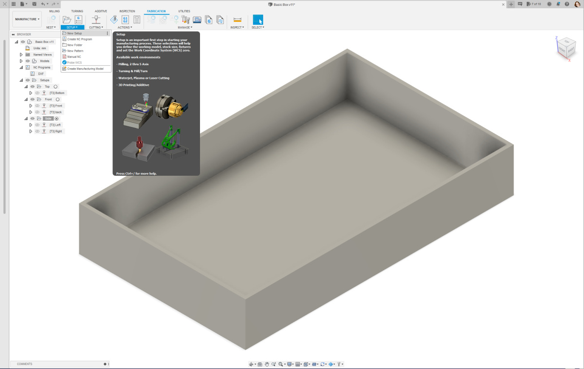 For laser cutting, you need to create a setup for each axis. If you've designed a project where the plates are neatly perpendicular to each other, you'll need 3 setups: one for the X-direction, one for the Y-direction, and one for the Z-direction. Just like I did in the example design I'm using here. For laser cutting, you need to create a setup for each axis. If you've designed a project where the plates are neatly perpendicular to each other, you'll need 3 setups: one for the X-direction, one for the Y-direction, and one for the Z-direction. Just like I did in the example design I'm using here. |
 For each setup, you need to configure a few things. The machine doesn't need to be set up directly. The files are not sent directly to a machine but are first processed in a drawing package that can work with vector files such as CorelDRAW, Illustrator, or Inkscape. For each setup, you need to configure a few things. The machine doesn't need to be set up directly. The files are not sent directly to a machine but are first processed in a drawing package that can work with vector files such as CorelDRAW, Illustrator, or Inkscape. |
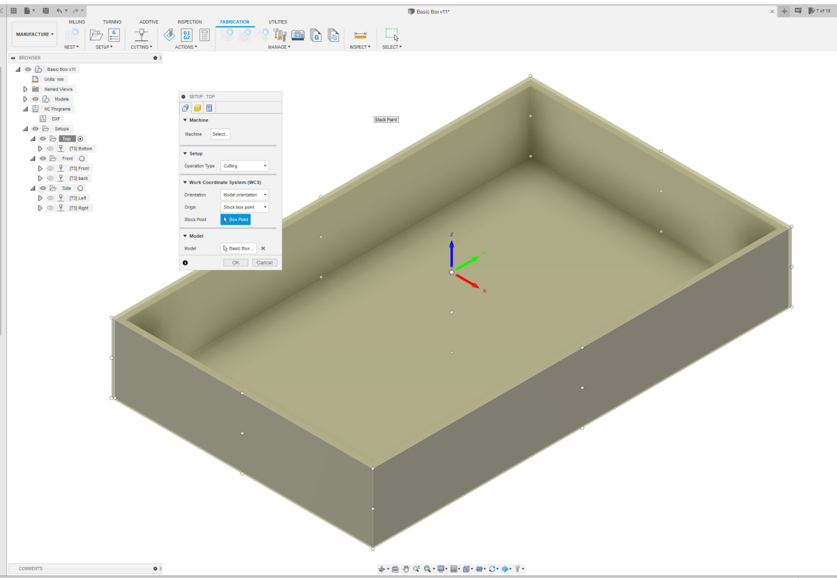
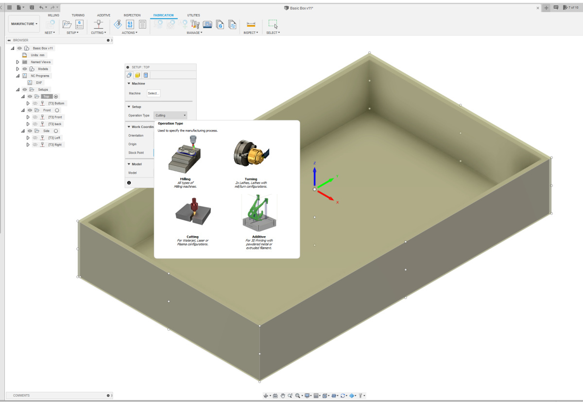 The operation type does need to be set up. This is cutting, as we're going to use it for a laser cutter. The operation type does need to be set up. This is cutting, as we're going to use it for a laser cutter. |
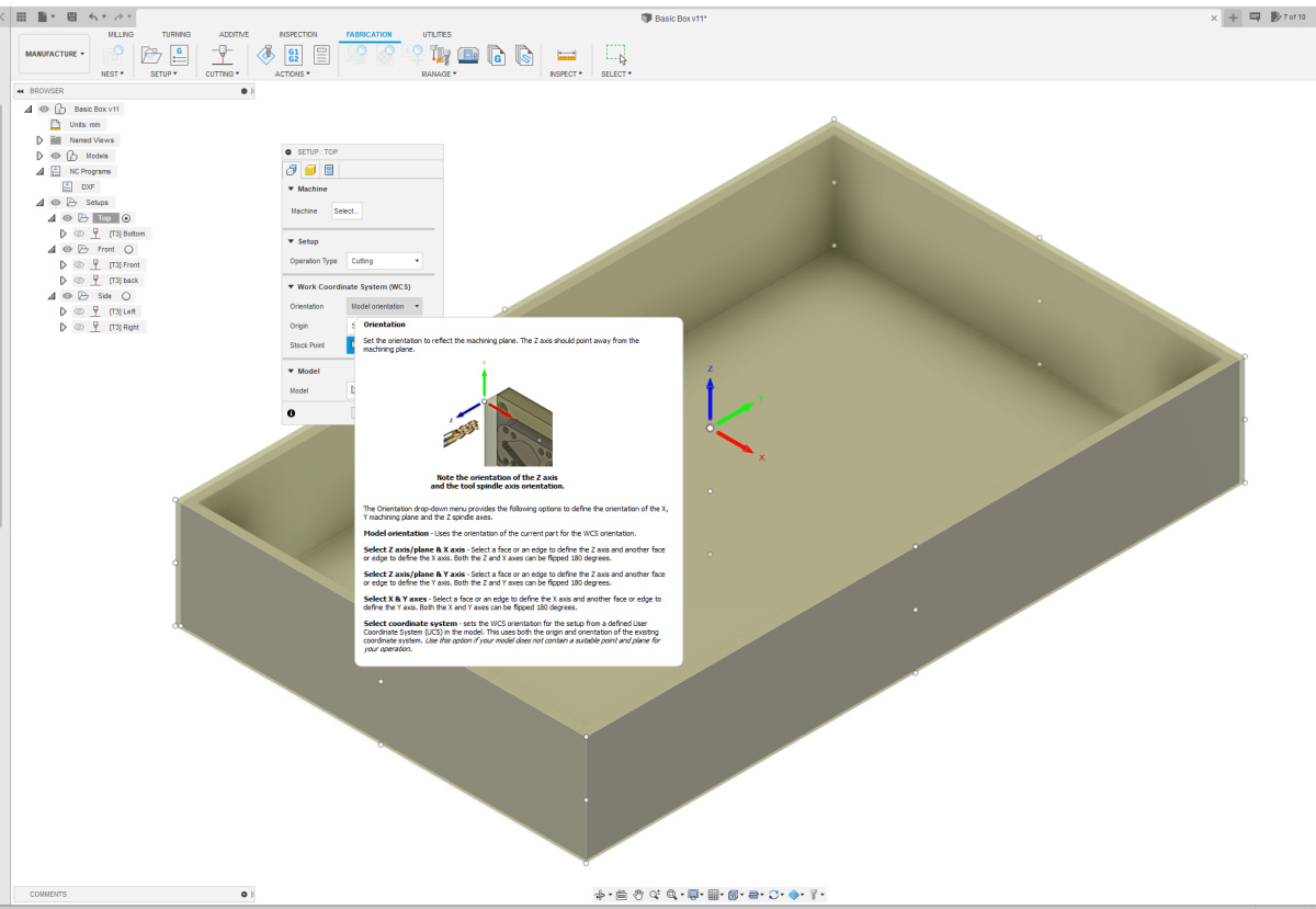 The orientation must also be set up. In the case of the Top view, from top to bottom, I can maintain "model orientation." Origin and Stock point do not need to be adjusted. The orientation must also be set up. In the case of the Top view, from top to bottom, I can maintain "model orientation." Origin and Stock point do not need to be adjusted. |
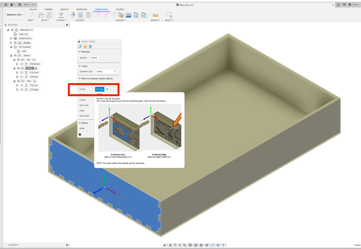 For the other setups, Front and Side, choose the option "Select Z-axis/Plane and X-axis." Then, select the correct plane in the Z-Axis box. For the other setups, Front and Side, choose the option "Select Z-axis/Plane and X-axis." Then, select the correct plane in the Z-Axis box. |
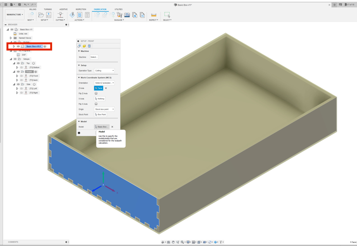 Finally, select your model in the Model section, as outlined in red in the image. Repeat the setup creation for all the directions used in your design. For simple boxes, this is typically three setups. Give your setups logical names so it's clear which parts of your design belong to each setup. Finally, select your model in the Model section, as outlined in red in the image. Repeat the setup creation for all the directions used in your design. For simple boxes, this is typically three setups. Give your setups logical names so it's clear which parts of your design belong to each setup. |
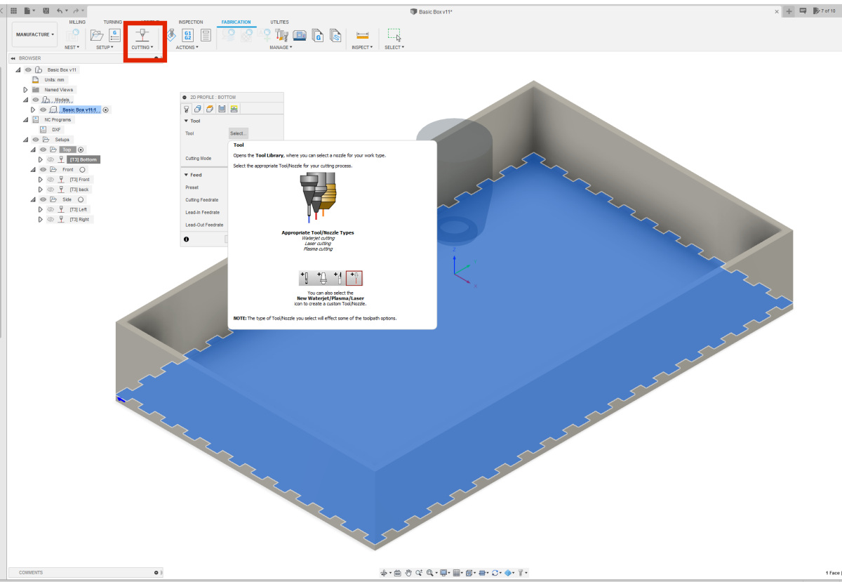 Now that you have all the setups, you can add the appropriate toolpaths (profiles) for each setup. A profile is the path that the laser cutter follows to cut out a part. Select the setup where you want to create a toolpath. You can do this by clicking on the circle next to the setup to put a dot in it. In this example, the Top setup is selected. Double-click on "Cutting" at the top of the menu bar in the "Fabrication" tab to create a new toolpath. Now that you have all the setups, you can add the appropriate toolpaths (profiles) for each setup. A profile is the path that the laser cutter follows to cut out a part. Select the setup where you want to create a toolpath. You can do this by clicking on the circle next to the setup to put a dot in it. In this example, the Top setup is selected. Double-click on "Cutting" at the top of the menu bar in the "Fabrication" tab to create a new toolpath. |
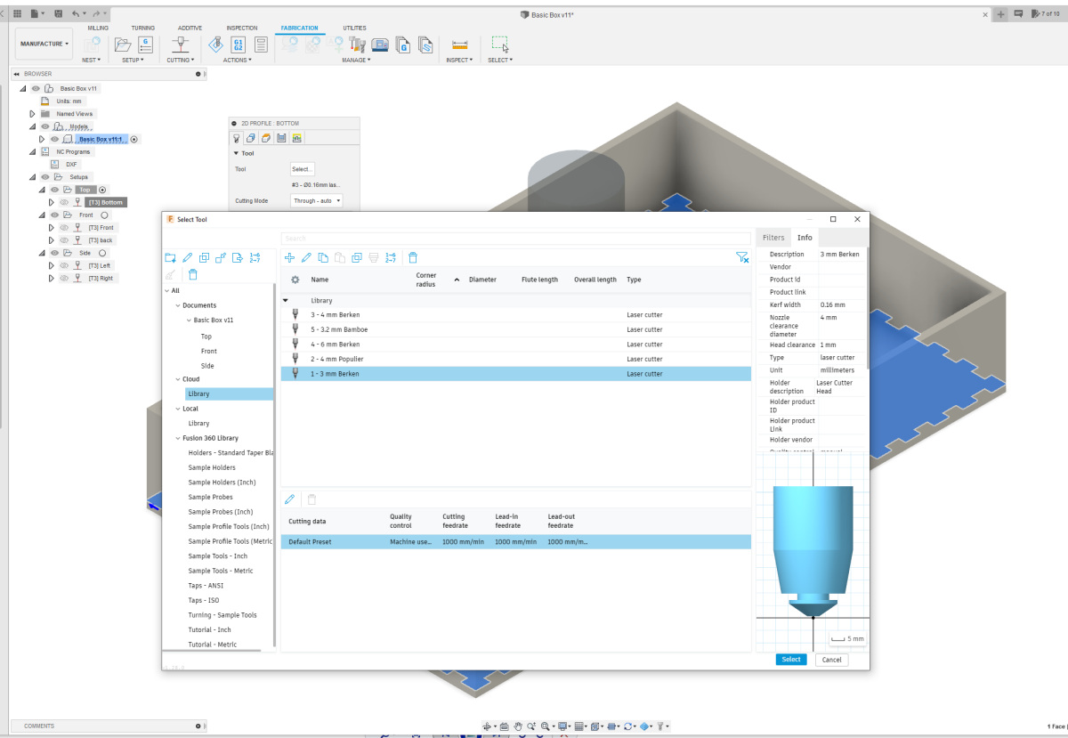 In this toolpath, the first thing you need to do is set the tool you want to use. You have several options by uploading the .json file to the Cloud under tools. Let's make use of that now. Click on the checkbox next to Tool to open a menu. On the left side of this menu, select iCloud, and then Library. You will now see several options. I used 3mm birch in my design, so I'll choose the bottom option. You can see on the left side that a kerf compensation of 0.16 mm is set for this option. In this toolpath, the first thing you need to do is set the tool you want to use. You have several options by uploading the .json file to the Cloud under tools. Let's make use of that now. Click on the checkbox next to Tool to open a menu. On the left side of this menu, select iCloud, and then Library. You will now see several options. I used 3mm birch in my design, so I'll choose the bottom option. You can see on the left side that a kerf compensation of 0.16 mm is set for this option. |
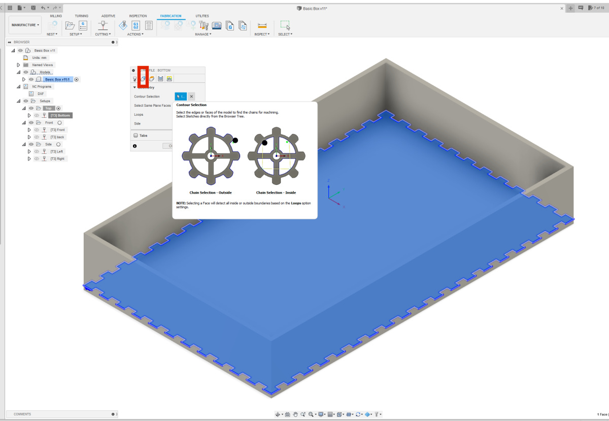 In the second tab, select the component for which you want to create the profile under "Contour Selection." There are a few options in that tab, but they are set correctly by default. In the second tab, select the component for which you want to create the profile under "Contour Selection." There are a few options in that tab, but they are set correctly by default. |
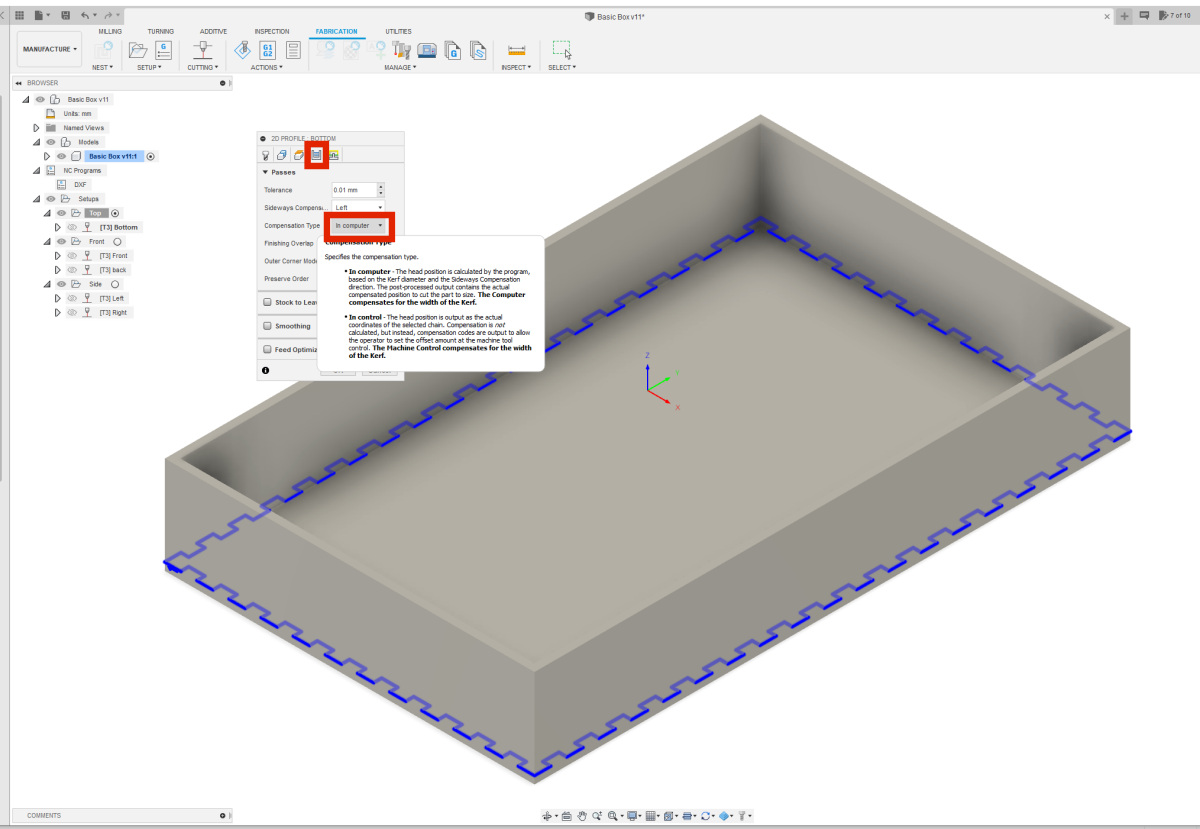 In the fourth tab, change the setting under "Compensation Type" to "In Computer." Forgetting this step will result in an empty exported file. So, this is a crucial setting. In the fourth tab, change the setting under "Compensation Type" to "In Computer." Forgetting this step will result in an empty exported file. So, this is a crucial setting. |
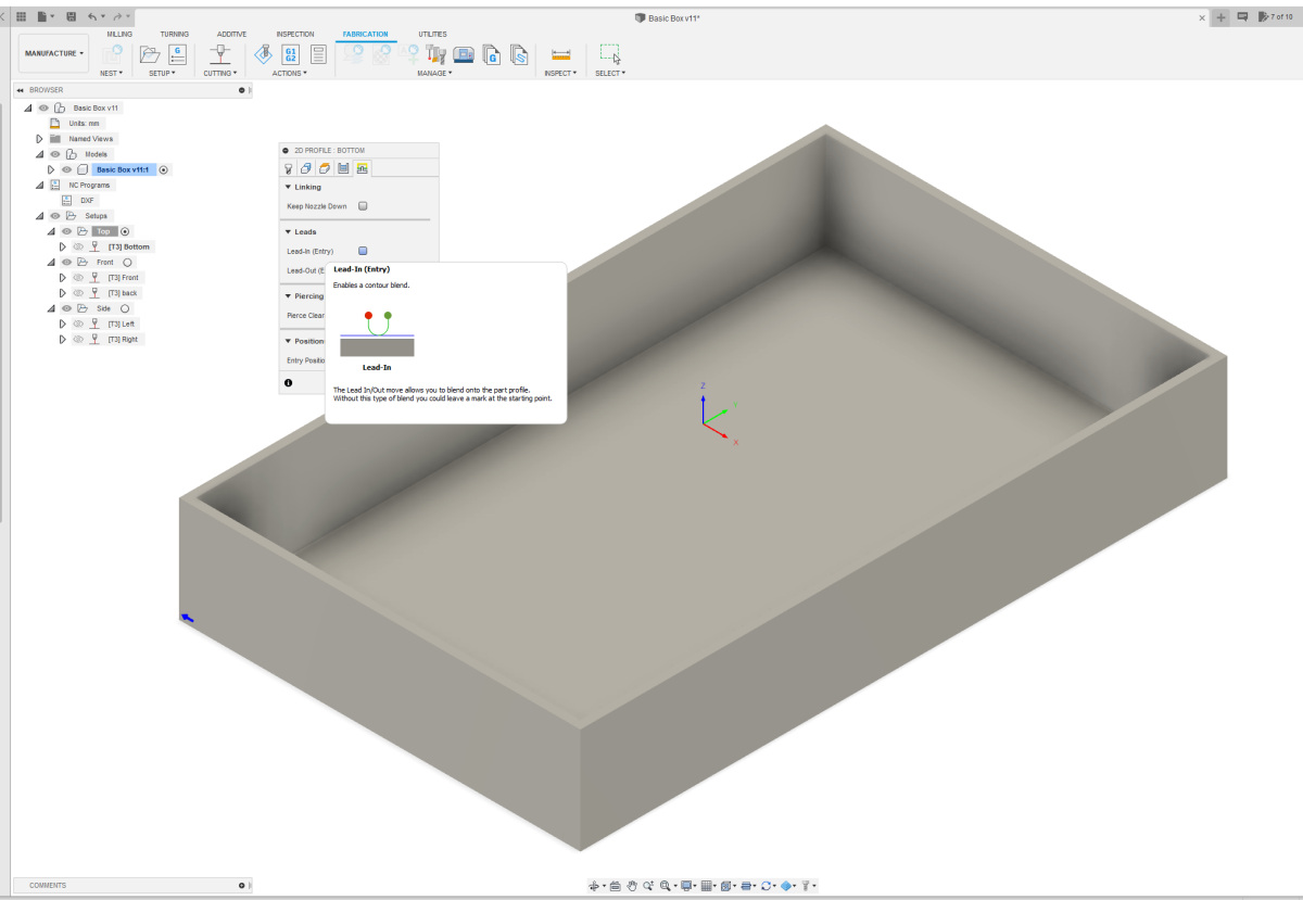 Finally, in the last tab, turn off the Leads. You can do this by unchecking the boxes next to Lead-In and Lead-Out. Repeat this for all profiles in your design. Once you've completed all the profiles, you can run your NC Program and export all profiles as DXF files. Finally, in the last tab, turn off the Leads. You can do this by unchecking the boxes next to Lead-In and Lead-Out. Repeat this for all profiles in your design. Once you've completed all the profiles, you can run your NC Program and export all profiles as DXF files. |
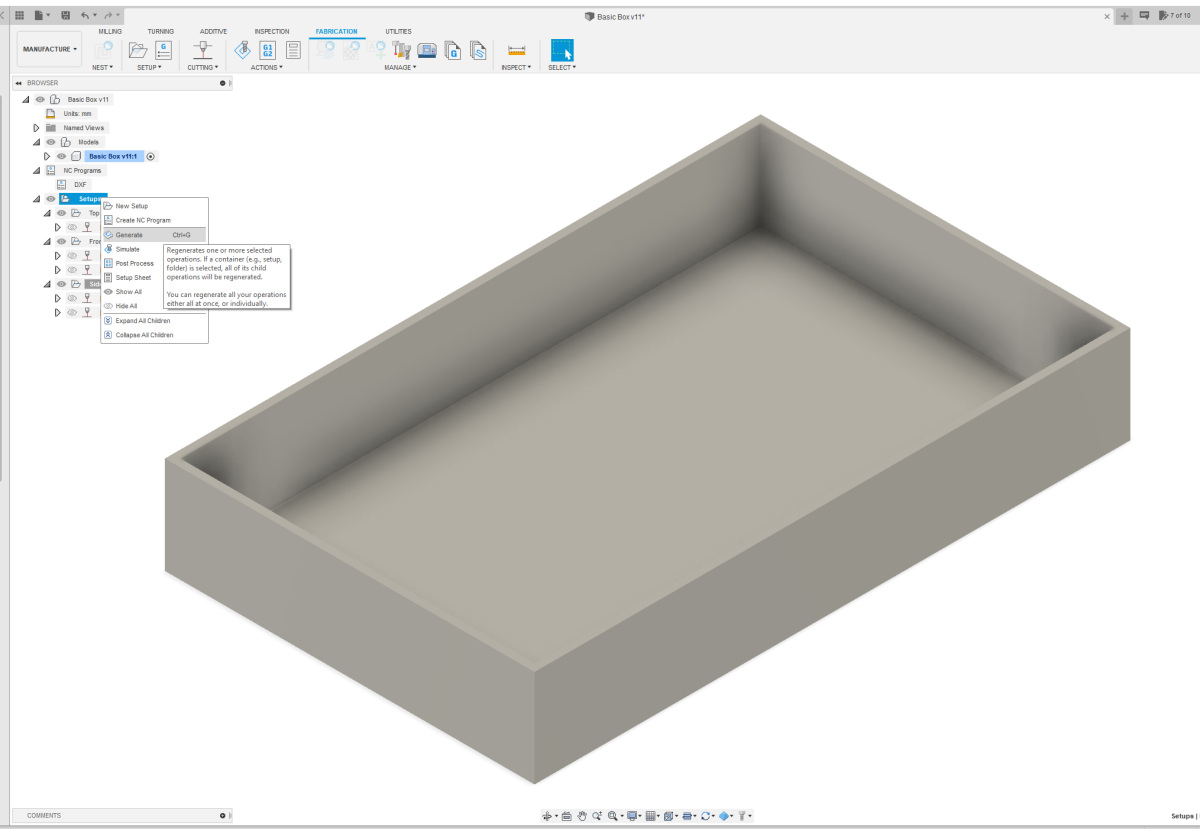 If you modify your design, you need to regenerate your profiles first. You do this by right-clicking on "Setups" and choosing the "Generate" option. Each profile is saved in a separate layer. A profile consists of many small pieces of lines, which you need to merge into a single line per profile so that you can place the different profiles neatly next to each other to prepare your design for sending to a laser cutter. You can do this in a drawing program that works with vector files. If you modify your design, you need to regenerate your profiles first. You do this by right-clicking on "Setups" and choosing the "Generate" option. Each profile is saved in a separate layer. A profile consists of many small pieces of lines, which you need to merge into a single line per profile so that you can place the different profiles neatly next to each other to prepare your design for sending to a laser cutter. You can do this in a drawing program that works with vector files. |